5 Appendix
5.3 Programming parameters for HCU
Page 94 Docu-No.: 0590020601-EN Rev. 1.6.0
5.3 Programming parameters for HCU
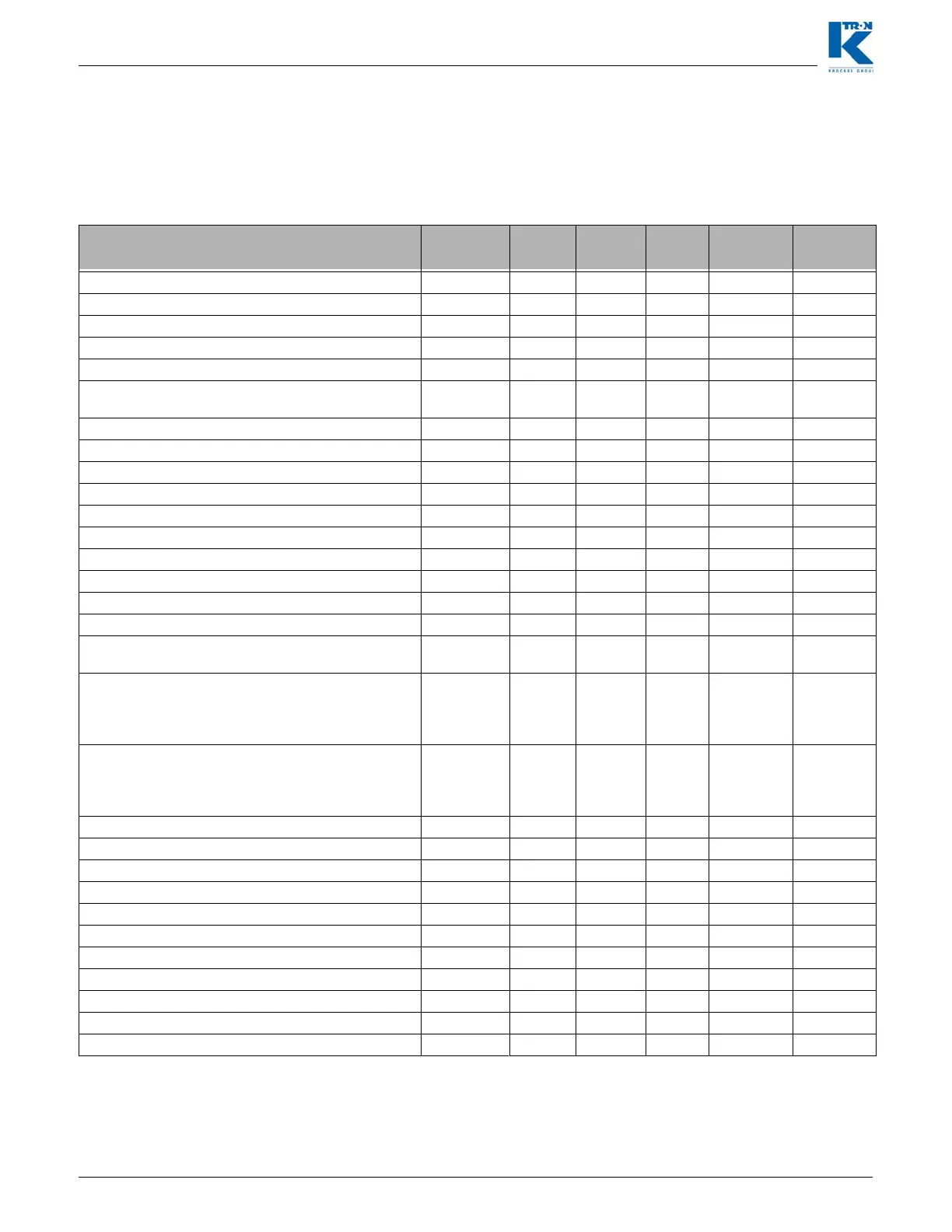
This table shows parameter number and description, which can be
entered in the section 1.10 for HCU loader control. 1.9.1For a detailed
description of all parameters see manual 0290023601.
Param Number/ Param description
KSU
Param.
Min Max Step Default
Actual
P1 – Load Timer (Cycle 3) Load 5 sec 300 sec 1 sec 20 sec
P2 – Clear Timer (Cycle 4) LineClr 0 sec 30 sec 1 sec 0 sec
P3 – Discharge Timer (Cycle 6) Disch 2 sec 90 sec 1 sec 10 sec
P4 – Filter Delay Timer Fill Dly 1 sec 5 sec 0.1 sec 5 sec
P5 – Filter Pulse Timer Fil Pul 0 sec 0.5 sec 0.1 sec 0.1 sec
P6 – Motor Timer (Cycle 1) Motor 30 sec 1620
sec
30 sec 5 min
P7 – Load Delay Timer (Cycle 2) Ld Dly 0 sec 20 sec 1 sec 5 sec
P8 – Discharge Delay Timer (Cycle 5) Dis Dly 0 sec 20 sec 1 sec 5 sec
P9 – Input Filter: Receiver Proximity Sensor In: Rec 0.1 sec 10 sec 0.1 sec 3 sec
P10 – Input Filter: Buffer Hopper Proximity Sensor In: BuH 0.1 sec 10 sec 0.1 sec 3 sec
P11 – Input Filter: Supply Hopper Proximity Sensor In: SuH 0.1 sec 10 sec 0.1 sec 1 sec
P12 – Input Filter: Remote Start In: Strt 0.1 sec 10 sec 0.1 sec 0.5 sec
P13 – Input Filter: Remote Stop In: Stop 0.1 sec 10 sec 0.1 sec 0.5 sec
P14 – Input Filter: Discharge Valve Switch In: DisV 0.1 sec 10 sec 0.1 sec 1 sec
P15 – Input Filter: Filter Pressure Switch In: FiPs 0.1 sec 10 sec 0.1 sec 1 sec
P16 – Input Filter: Discharge Request In: DiRe 0.1 sec 10 sec 0.1 sec 1 sec
P17 – Input XOR Mask Xor Msk 7F(dec12
7)
P18 – Oper M (Operating Mode)
1 = Self contained with discharge valve, 2 = Single
central with discharge valve, 3 = Self contained, 4 =
Single Central
Oper M 1
P19 – Clean Filter
0 = disables all cleaning, 1 = clean during discharge
cycle, 2 = clean during load cycle, 3 = clean during
both discharge and load cycles.
Clean M 1
P20 – Discharge Mode, 1 = Fill mode, 2 = LWF mode Disch 1
P21 – Controller Address HCUAdd 0x01
P22 – Controller Software Version HCU SW
P23 – Supply Hopper Low Alarm Timer Al ShLo 0 sec 600 sec 10 sec 0 disable
P24 – Differential Pressure High Alarm Timer Al DPHi 0% 100% 1% 0 disable
P25 – Load Cycle Alarm Counter Al Cycle 0 cycle 20 cycle 1 cycle 0 disable
P26 – Discharge Valve Alarm Timer Al Valve 0 sec 15 sec 1 sec 10 sec
P27 – On/Off Counter O/F Cnt N/A
P28 – Run Time Counter Run Cnt N/A
P28 – Handheld display Software version HSU SW N/A
P63 – Digital input states Dig In N/A
 Loading...