MULTICAL® 403
Kamstrup A/S · Technical description · FILE100000166_B_EN-55121689_M1_07.2023
1.2 Electronic structure
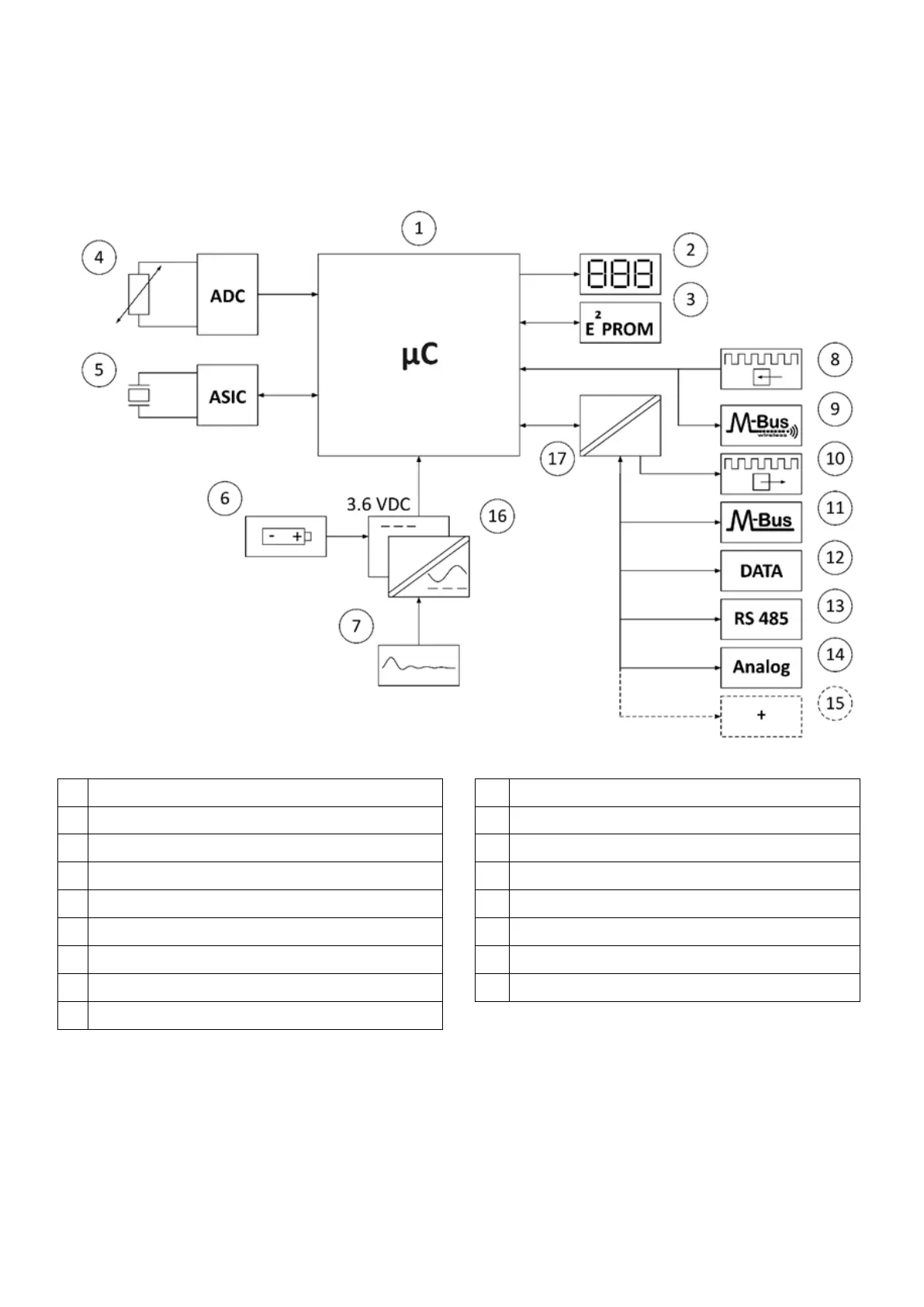
The electronic construction of MULTICAL® 403 is shown in the block diagram below. One of the described modules,
which include pulse inputs or pulse outputs in addition to data communication, can be mounted in the module bay
of MULTICAL® 403. During operation MULTICAL® 403 only includes one of the seven supply module types.
Microcontroller
Pulse outputs
Display, eight-digit seven-segment + symbols
M-Bus
Non-volatile memory, E² PROM
Data communication
Temperature sensors Pt500
RS485
Flow sensor, piezo elements
Analog 0/4…20 mA
Battery, 2 x A-cell, 1 x C-cell or 1 x D-cell
… and even more communication options
Linear power supply, 24 VAC or 230 VAC.
Galvanically separated power supplies
Pulse inputs
Galvanically separated communication modules
Wireless M-Bus
Note: The arrows in the figure indicate the signal direction