MULTICAL® 403
Kamstrup A/S · Technical description · FILE100000166_B_EN-55121689_M1_07.2023
8 Flow sensor
Throughout more than 25 years ultrasonic measurement has proved accurate and the most long-term stable
measuring principle for heat measurement. Experience from repeated reliability tests carried out in Kamstrup’s
accredited long-term test equipment and at AGFW in Germany as well as from ultrasonic meters in operation has
documented the long-term stability of ultrasonic meters. (see e.g. report on random sampling of flow sensors,
Kamstrup A/S doc. No. 5811-060)
8.1 Measuring principles
Within ultrasonic flow measuring there are two main principles: the transit time method and the Doppler method.
The Doppler method is based on the frequency change which occurs when sound is reflected by a moving particle.
This is the effect you experience when a car passes you. The sound (the frequency) decreases when the car passes
by.
The transit time method used in MULTICAL®
403 utilizes the fact that it takes an ultrasonic signal sent in the opposite
direction of the flow longer to travel from sender to receiver than a signal sent in the same direction as the flow.
A piezo-ceramic element is used for transmitting and receiving ultrasound. The thickness of the element changes
when exposed to an electric field (voltage) and thereby it functions as a transmitter of ultrasound. When the
element is mechanically influenced, it generates a corresponding electric voltage, and thus functions as a receiver of
ultrasound.
8.2 Signal path and flow calculation
The most important elements of the signal path in MULTICAL® 403 are shown in Figure 13: Piezo-electric elements
transmit and receive the ultrasound signal, which is reflected into and through the measuring tube to the receiver .
Due to superposition of velocities of water and sound signal, ultrasound spreads faster with the flow than against the
flow. As it is proven by the calculations below, the average flow velocity is directly proportional to the transit time
difference of ultrasound signals which are sent with or against the flow.
In small meters (q
p
0,6…2,5 m³/h) a construction with a sound path parallel to the pipe axis is used. The emitted
sound waves cover the pipe area of these meters reasonably well and thus the measuring signal is stable enough
towards flow variations along the pipe diameter. In big meters (q
p
3,5…15 m³/h) a construction with a triangular
sound path is used to make sure that flow variations along the pipe diameter are covered too in these meters. The
measuring signal here results in a linear integration along the sound path, which levels possible dissymmetry of the
flow profile in the meter.
p
0,6…2,5 m³/h
Parallel measurement
p
3,5…15 m³/h
Triangular measurement
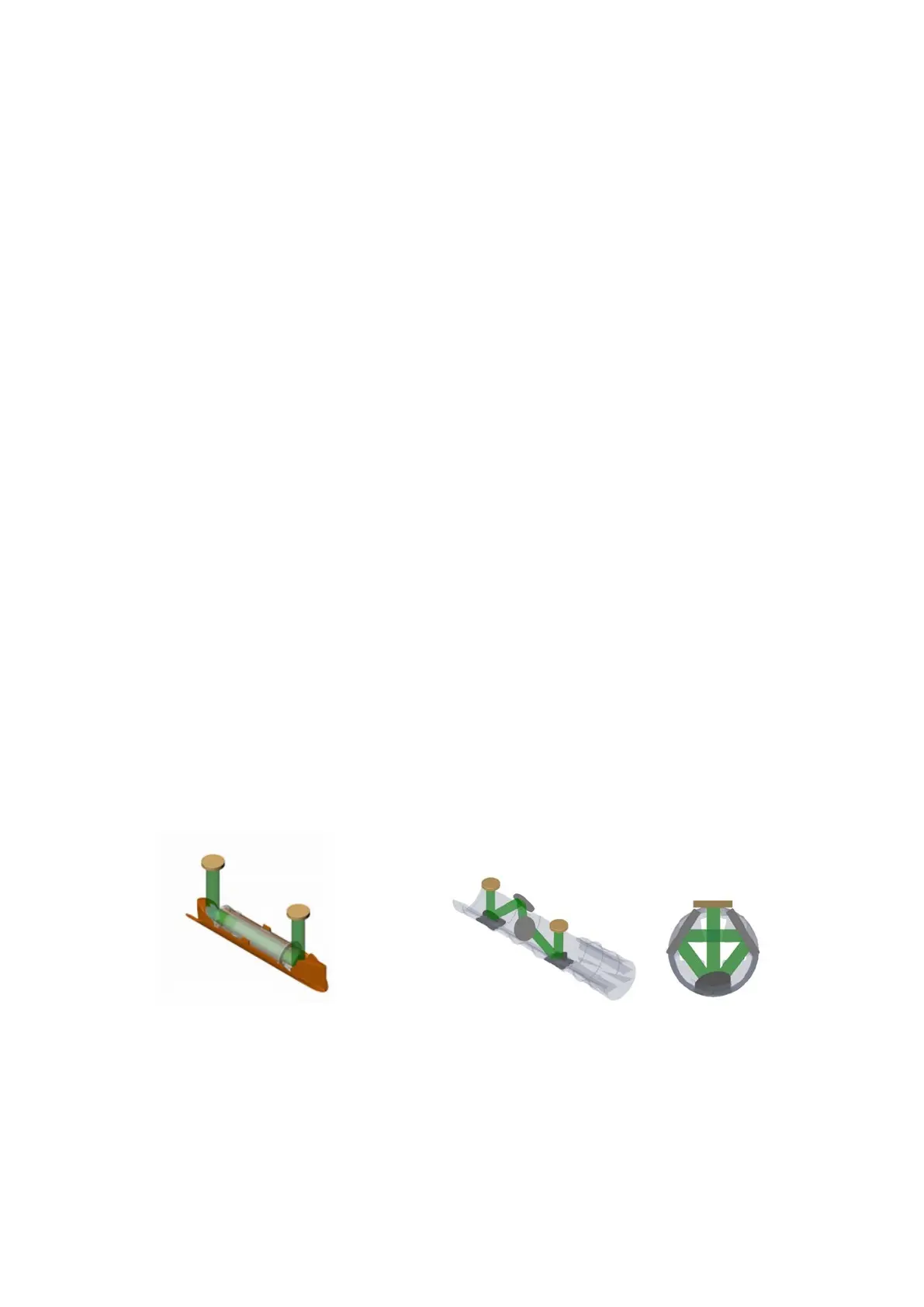
Figure 13: Signal paths in MULTICAL® 403. Sound signals are sent from the transducers via 2 or 4 reflectors,
depending on the construction. For small meters (q
p
0,6…2,5 m³/h) a parallel sound path is sufficient. To
cover flow variations along the pipe diameter (flow profile) in the flow sensor a triangular sound path is
used in big meters q
p
3,5…15 m³/h). In both constructions the transit times of the signal with and against
the flow vary.