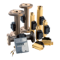
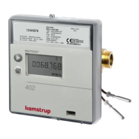
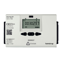
MULTICAL® 403
Kamstrup A/S · Technical description · FILE100000166_B_EN-55121689_M1_07.2023
For calculation of the transit time difference we only view a simple example with a sound patch parallel to the
measuring pipe. The signal path along the flow is crucial and the transit time to the measuring distance is calculated
as:
where:
is the transit time from sender to receiver of the sound signal along the measuring distance l [s]
is the measuring distance [m]
is the sound propagation velocity in stagnant water [m/s]
is the average flow velocity of water [m/s]
The transit time difference can be expressed as the difference between the absolute time of the signal sent against
the flow (-) and the signal sent with the flow (+).
which can also be written as:
22
2
))((
)()(
vc
v
lt
vcvc
vcvc
lt
−
=∆⇒
+−
−−+
=∆
As
,
can be omitted and the formula reduced as follows:
Thus, we know the basic connection between the average flow velocity and the transit time difference.
The transit time difference in a flow sensor is very small (nanoseconds). Therefore, the time difference is measured
as a phase difference between the two 1 MHz sound signals in order to obtain the necessary accuracy.
Furthermore, MULTICAL® 403 takes the influence of the temperature of the water into account i.e. the built-in ASIC
uses the sound velocity at the water’s current temperature in connection with the flow calculations.
The flow (volume flow rate) is then determined by measuring the transit time difference, calculate the average flow
velocity and multiply it by the area of the measuring tube:
where:
is the flow (volume flow rate)
Is the area of the measuring pipe
The volume
passing through is finally calculated as a time integration over the flow (multiplication of (cross
section constant) flow by time).
 Loading...
