MULTICAL® 403
Kamstrup A/S · Technical description · FILE100000166_B_EN-55121689_M1_07.2023
3.2.1 Flow sensor position >A<
The code A indicates installation of flow sensor in inlet or outlet. As the density and heat capacity of water vary with
temperature, the calculator must correct this based on the installation position (A-code). Incorrect programming or
installation leads to error of measuring. Please see paragraphs 4.2 and 4.5 for further details on installation of flow
sensor in inlet and outlet as far as heat and cooling installations are concerned.
3.2.2 Measuring unit >B<
The B-code indicates the measuring unit used in the energy register. The options are GJ, kWh or MWh.
3.2.3 Flow sensor coding >CCC<
The CCC-code optimises the display resolution for the selected flow sensor size. At the same time the type approval
regulations as to minimum resolution and maximum register overflow are observed. The CCC-codes are divided into
three tables for standard resolution and high resolution respectively.
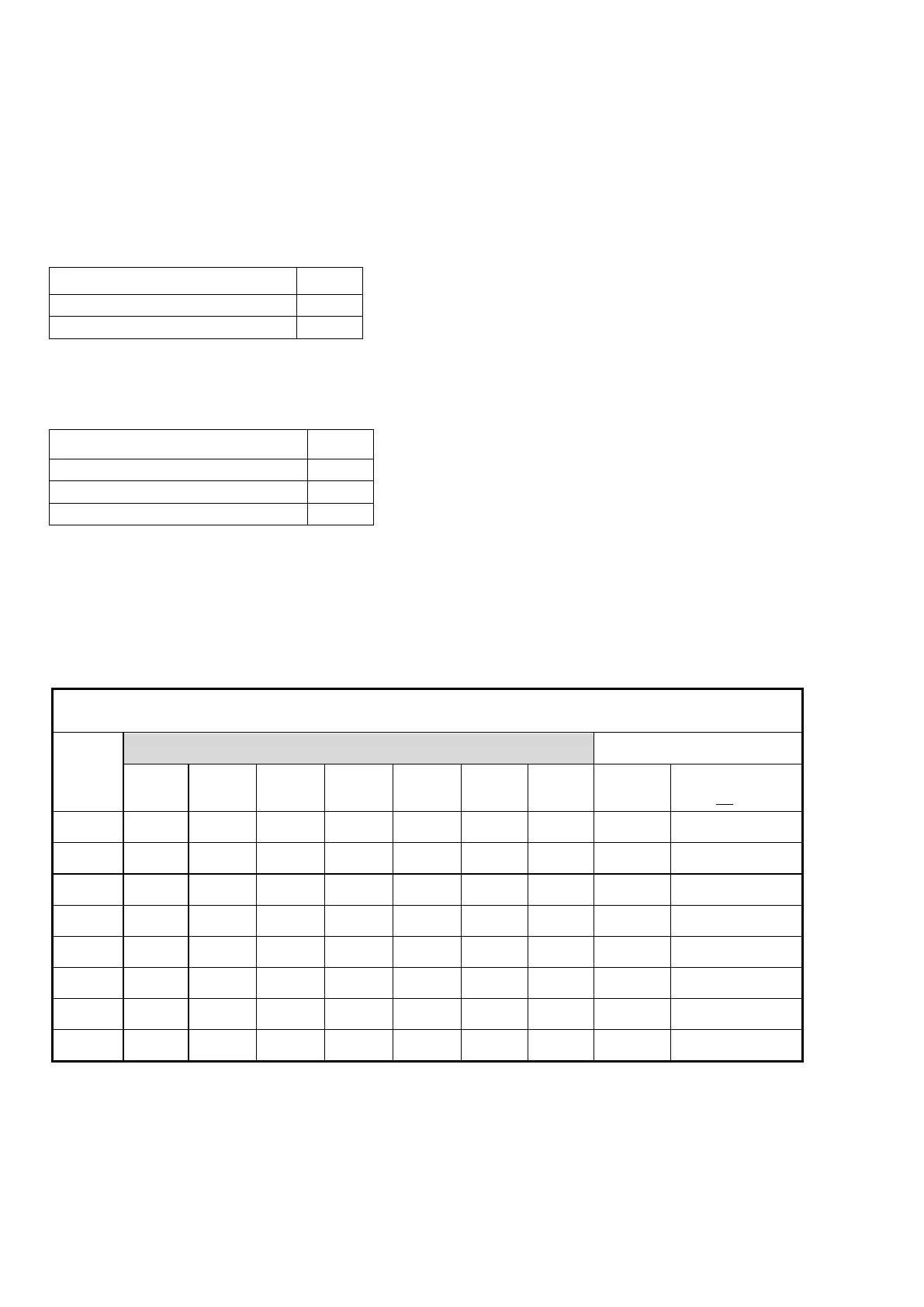
Standard CCC-codes with 7 digits
7 digits CCC-table for MULTICAL
403 (standard)
Number of decimals in display
0 3 2 2 0 - 1 0,6 1x-3x
0 3 2 2 0 - 1 1,5 4x-5x-7x-8x-9x
0 3 2 2 0 - 1 2,5 Ax-Bx
- 2 1 1 0 - 1 3,5 Dx
- 2 1 1 0 - 1 6,0 Fx-Gx
- 2 1 1 0 - 1 10 Hx-Jx
- 2 1 1 0 - 1 15 Kx
- 1 0 0 0 - 1 15 Kx