MULTICAL® 403
Kamstrup A/S · Technical description · FILE100000166_B_EN-55121689_M1_07.2023
4.5 Operating pressure of MULTICAL® 403
In connection with installations it has proved practical to work with minimum the pressure mentioned in table 2
below:
Recommended back
pressure
[bar]
Recommended back
pressure
[bar]
0,6…10 1 1,2...20 2
15 1,5 30 2,5
Table 2: Recommended back pressure at various flow sensor sizes
The values in the table apply to temperatures up to approx. 80 °C
The purpose of recommended back pressure is to avoid measuring errors as a result of cavitation or air in the water.
Cavitation does not necessarily happen in the sensor itself, but can also occur as air bubbles created by pump
cavitation and regulating valves mounted before the sensor. It can take considerable time until such bubbles have
been dissolved in the water.
Furthermore, water can include dissolved air. The amount of air which can be dissolved in water depends on
pressure and temperature. This means that air bubbles can be formed due to a pressure drop in the installation, e.g.
caused by a velocity rise in a contraction or above the sensor.
The risk of influence from the above is reduced by maintaining a fair pressure in the installation.
In relation to table 2, the steam pressure at current temperature must be considered too. The values in the table
apply to temperatures up to approx. 80 °C. The graph in Diagram 2 applies to higher temperatures. Furthermore, it
must be taken into consideration that the mentioned pressure is the back pressure at the flow sensor outlet and that
the pressure is lower in a contraction than before one, e.g. in case of cones. This means that the pressure, if
measured elsewhere in the installation, may differ from the pressure at the flow sensor.
The explanation of pressure drop due to velocity increase is found by combining the continuity equation and
Bernoulli’s equation. The total energy from the flow will be the same at any cross section.
It can be reduced to: P + ½ρv
2
= constant.
where: P = pressure,
ρ
=
density, v = velocity.
Dimensioning a flow sensor you must take the above into account, especially if the sensor is used in the area
between q
p
and q
s
described in EN 1434 , and in case of heavy contractions of the pipe.
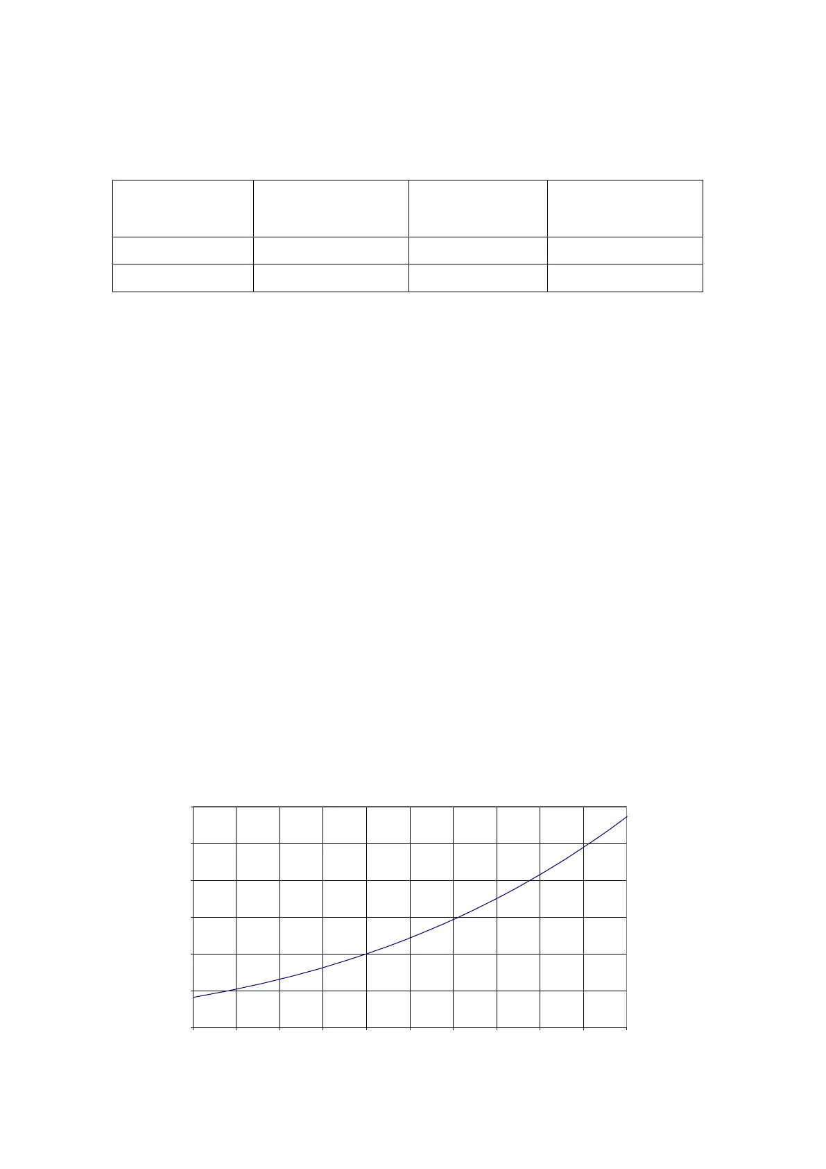
Diagram 2. Steam pressure as a function of temperature
0
0,5
1
1,5
2
2,5
3
80 85 90 95 100 105 110 115 120 125 130
[bar]
[°C]
Steam pressure