Page 7.2 - 8 COMBIVERT F5-A, -E, -H © KEB, 2012-10
Analog in- and outputs
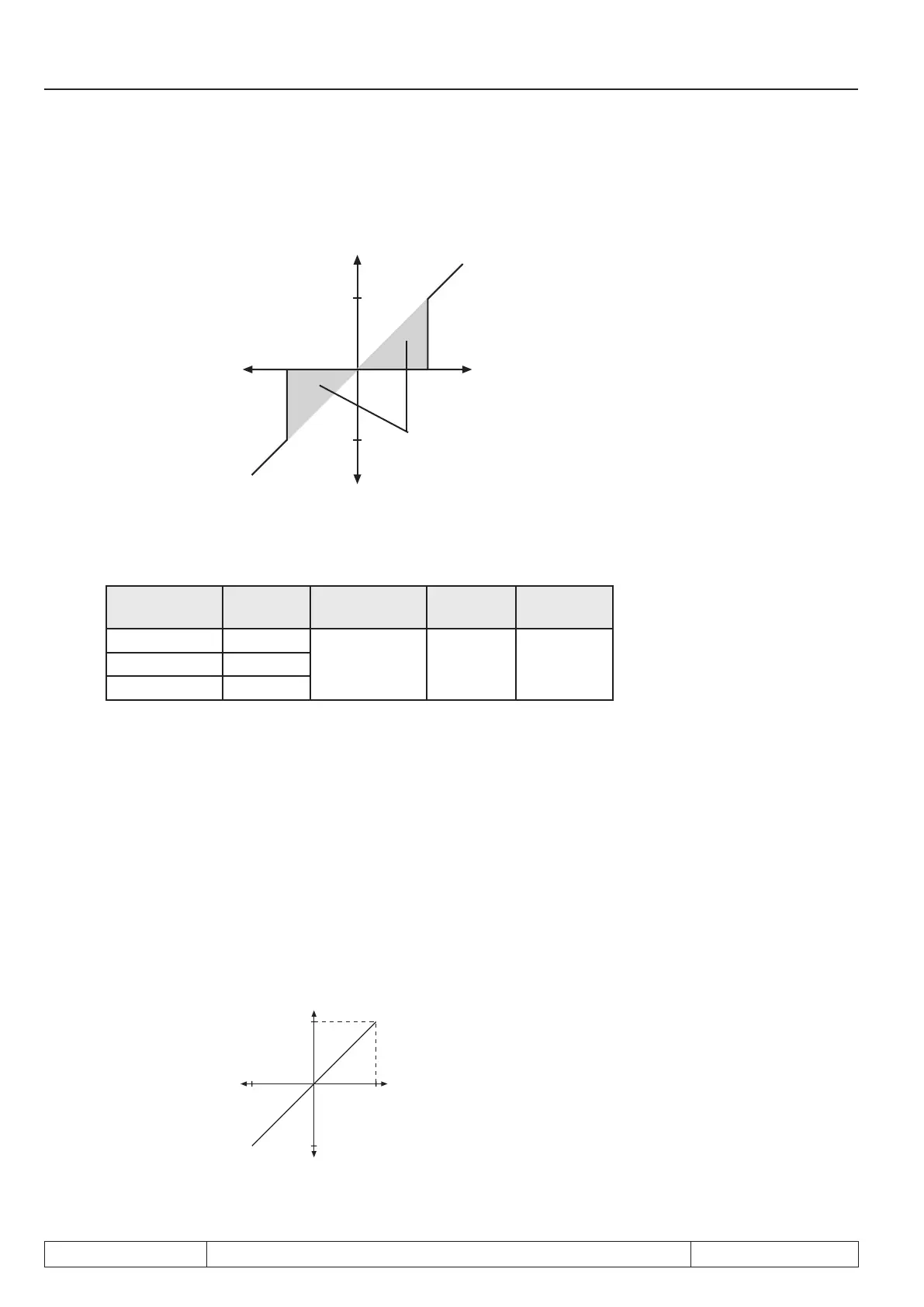
Fig. 7.2.5 Zero point hysteresis
Output signal (for further signal processing)
-10%
10%
10%
-10%
fade-out range
Input signal co-
ming from the
noise lter
Value range
Input Parameter Value range Resoluti-
on
Default
value
AN1 An.04
0...±10% 0,1% 0,2%AN2 An.14
AN3 An.24
7.2.6 Amplieroftheinputcharacteristic(An.05...07,An.15...17,An.25...27)
With these parameters the input signals can be adapted in X and Y direction as well as in the rise to the
requirements. In the case of factory setting no zero point offset is adjusted, the rise (gain) is 1, i.e. the input
value corresponds to the output value of this step (see Fig. 7.2.6.a). The output value is calculated according
to following formula:
Out = Amplication • ( In - Offset X) + Offset Y
Fig. 7.2.6.a Factory setting: no Offset, Gain 1
Output value (Out)
Input value (In)

 Loading...

