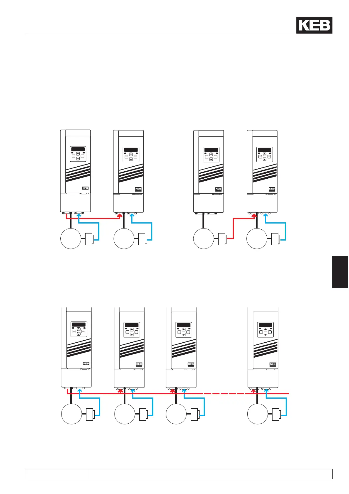
7.12.3.2 Synchronous mode / premise
For the synchronous module, the incremental signals from the encoder of the master drive must be passed on
to the slave.
START
STOP
FUNC.
SPEED
ENTER
F/R
ANTRIEBSTECHNI K
START
STOP
FUNC.
SPEED
ENTER
F/R
ANTRIEBSTECHNI K
START
STOP
FUNC.
SPEED
ENTER
F/R
ANTRIEBSTECHNI K
START
STOP
FUNC.
SPEED
ENTER
F/R
ANTRIEBSTECHNI K
X3B X3A X3B X3BX3A X3A
3
~
3
~
3
~
3
~
closed-loop
master drive
closed-loop
slave drive
master drive
closed-loop
slave drive
If more than one slave is connected, there are two different variations for assembling the master-slave-chain:
direct transfer of the signals from the output of the master encoder interface to all slaves.
START
STOP
FUNC.
SPEED
ENTER
F/R
ANTRIEBSTECHNI K
START
STOP
FUNC.
SPEED
ENTER
F/R
ANTRIEBSTECHNI K
START
STOP
FUNC.
SPEED
ENTER
F/R
ANTRIEBSTECHNI K
START
STOP
FUNC.
SPEED
ENTER
F/R
ANTRIEBSTECHNI K
X3B X3A X3B X3BX3A X3A
3
~
3
~
3
~
3
~
closed-loop
master drive
closed-loop
slave drive1
closed-loop
slave drive 2
closed-loop
slave drive X
Ec.20 encoder operating mode = 1
(input + without terminating resistor)
Ec.20 encoder operating mode = 0
(input + with terminating resistor)
Posi- and synchronous operating
© KEB, 2012-10 COMBIVERT F5-A, -E, -H Page 7.12 - 15
7

 Loading...

