7.12.5.2 Contouring control mode / settings
All parameters can be specified in bus-synchronous operation. Typically, this operating mode is used for the
contouring control mode. The activation of this mode is done in parameter PS.00 or via the control word.
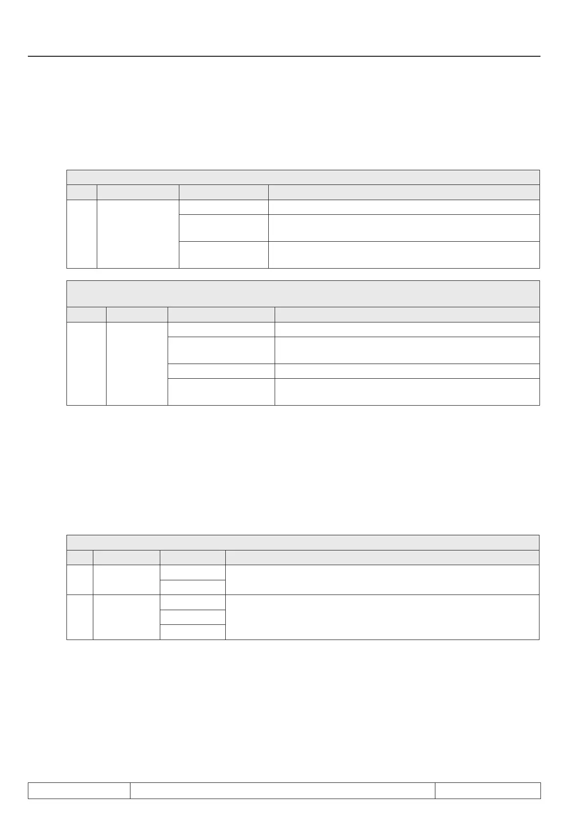
PS.00: Posi / synchronous mode
Bit Meaning Value Explanation
0...2
Posi / synchro-
nous mode
0...5 Without function for contouring control
6: Contouring
control
Selection of operating mode contouring control
7: via control word
The operating modes are selected via the control word
(Sy.43 or Sy.50).
Sy.50: control word (low) /
Sy.43: control word (long)
Bit Meaning Value Explanation
12 / 13
Operating
mode
0: off
4096: synchronous
running
Selection of operating mode synchronous running
8192: positioning Selection of operating mode positioning
12288: Contouring
control
Selection of operating mode contouring control
To activate the contouring control mode, the digital input assigned with the function "posi / synchronous" must
be set.
In contouring control mode, the drive is positioned via the setting of a position setpoint value in the bus-syn-
chronous grid. The control, therefore, does not give the nal target position but the set point position for each
individual cycle.
The inverter calculates the speed required to reach the position setpoint in one bus cycle. The setting of the
position setpoint can be done via PS.24 "index position" or via PS.34 "ctm position".
PS.33 "contouring mode setpoint source" determines which parameter provides the setpoint position.
PS.33: Source contouring mode position
Bit Meaning Value Explanation
0
Source posi-
tion setting
0: PS.34
The position is stored as set position by writing on PS.34. The value is
stored as set position by writing on PS.24.
1: PS.34, 24
1, 2
Source
speed setting
0: calculated
Parameter „set speed value“ (SY.52) has 1 rpm in all resolution
modes. Parameter „reference setting“oP.03 is used in order to select a
high resolution.
2: SY.52
4: oP.03
7.12.5.3 Contouring control mode / write / read data
For the bus-synchronous operation, the read and write data that are to be transmitted with each bus cycle must
be defined. In the parameters Sy.24, Sy.26 and Sy.28, the bus addresses of the parameters that are to be pro-
vided bus-synchronously by the customer control must be set.Only 3 parameters can be selected (one 32 bit
parameter and two 16 bit parameters).
The set position (32 bit parameter) must always be preset bus-synchronously for the contouring control mode.
Page 7.12 - 78 COMBIVERT F5-A, -E, -H © KEB, 2012-10
Posi- and synchronous operating

 Loading...

