Torque display and -limiting
© KEB, 2012-10 COMBIVERT F5-A, -E, -H Page 7.8 - 7
7
EMC voltage constant (dr.26) x actual speed
——————————————————————
1000 rpm
pulse wheel voltage =
Attention:
There are several disadvantages contrary to the advantage of higher maximum speed:
- the drive is more prone to vibrations in the base speed range
- not all motors are suitable for eld weakening operation
- a higher current is required for the same torque due to the magnetizing current demand
- the rotor position information must be very exactly. A system position error (e.g. in case of inaccurate
encoder mounting) can make the drive uncontrollable.
7.8.3.2.1 Determination of the magnetizing current limit (dS.13)
There is a specic 'ideal' magnetization current limit for each motor. The available eld-weakening range is very
small if the limit is too small.
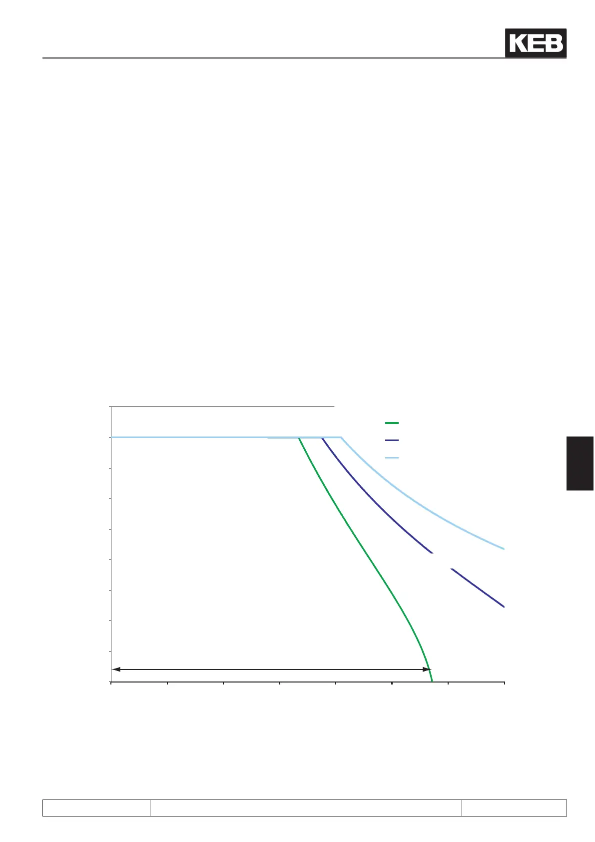
The following picture shows the connexion between the maximum reachable torque and the magnetizing cur-
rent limit dS.13.
Picture 7.8.3.2.1a Magnetizing current limit
Drehzahl [U/min]
Motormoment [Nm]
Moment (dS.13 = 0)
Moment (dS.13 = 0,5 * In)
Moment (dS.13 = In)
Grunddrehzahlbereich
Feldschwächbereich
If the magnetizing current limit is selected too high, the available torque becomes smaller again. In addition,
too high value for dS.13 can cause the maximum voltage controller to "hang". That means: for setting the ma-
gnetising current, more voltage is used than is gained from the eld weakening. The voltage remains too high.

 Loading...

