Page 7.8 - 14 COMBIVERT F5-A, -E, -H © KEB, 2012-10
Torque display and -limiting
7.8.6 Display of the torque-related motor load (ru.90)
The load of the total drive can be displayed with ru.90.
The calculation of ru.90 depends on the mode.
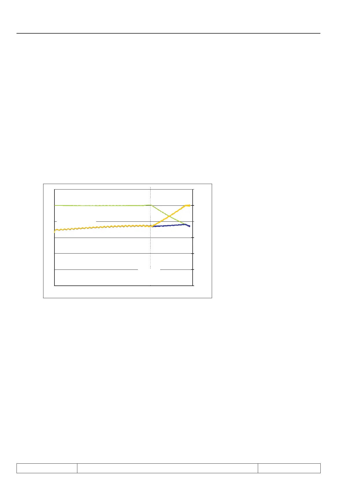
7.8.6.1 Mode 1: „Torque reference level“ Le 27 = 0
The calculation of ru.90 depends on the formula:
Actual torque display (ru.12)
———————————————————————
Actual torque limit (ru.47
mot.
respectively ru.48
gen.
)
ru.90 =
Figure 7.8.6.1 LE.27 = 0
Drehzahl [U/min]
Moment [Nm]
0
20
40
60
80
100
120
max.Drehmoment in % (ru.90)
Sollmomentgrenze motorisch (ru.47)
Feldschw.-
drehzahl
(dr.18)
Istmoment (ru.12)
max. Drehmoment in % (ru.90)
7.8.6.2 Mode 2: „Torque reference level“ Le 27 unequal 0
The maximum thermally permissible torque - i.e., in the base speed range, the rated torque, and the range
higher than the rated speed, the rated torque attenuated following a 1/x-function - is taken as 100% utilization
of the motor.
The programmed speed-torque characteristic is accepted as 100% utilization of the inverter. This characteristic
consists of the torque limits in the cS-Parameters (e.g. cS.19) and the limiting characteristic in the dr-Parame-
ters (e.g. dr.15...dr.18).
The adjusted value in parameter "torque reference level“ (LE.27) corresponds to 100% utilization in the applica-
tion. This could be e.g. the torque which is permanent permissible for the mounted worm gears or the mounted
gear box.
The smallest of the 3 values indicates the torque with which the whole drive can be loaded permanently at
the corresponding speed. This torque is the reference torque for the calculation of parameter "max torque in
percent" (ru.90).

 Loading...

