Page 7.12 - 30 COMBIVERT F5-A, -E, -H © KEB, 2012-10
Posi- and synchronous operating
PS.00: Posi / synchronous mode
Bit Meaning Value Explanation
13 Start with speed
0: PS.00
/ off
The set speed is determined via the Op-Parameters after activation of
the posi module upto the rst edge startposi.
8192:
PS.00 / on
The initial setpoint speed is started after activation of the posi module
upto the rst edge startposi.
Parameter ru.00 shows, with the progress message "121: ready for positioning", that the positioning mode has
been activated. But the drive is in position controlled operation only after the rst "start positioning". The positi-
on controlled operation is ended as soon as the positioning module is deactivated.
7.12.4.4 Position normalisation
The resolution of the position display/ setting is done in increments and depends on the used encoder system.
The following cases must be differentiated:
7.12.4.4.1 Position control by the motor encoder
Position control is based on the motor position encoder. I.e., the position values refer to the motor position.
The number of increments per motor revolution amounts to "encoder increments per revolution" x 2
"multiple
evaluation"
.
If encoder interface 1 (X3A) is used, Ec.01 "encoder 1 (inc/r)" and Ec.07 "enc.1 trigger" must be used for the
calculation.
If encoder interface 2 (X3B) is used, the number of increments per motor revolution must be calculated corre-
sponding of Ec.11 "encoder 2 (inc/r)" and Ec.17 "enc.2 trigger".
If the position control is done directly on the motor encoder, the same encoder channel must be selected in
PS.01 "master source" and cS.01 "act. source".
Value 1 (i.e. gear factor numerator = gear factor denominator) must be selected for the gear factors .
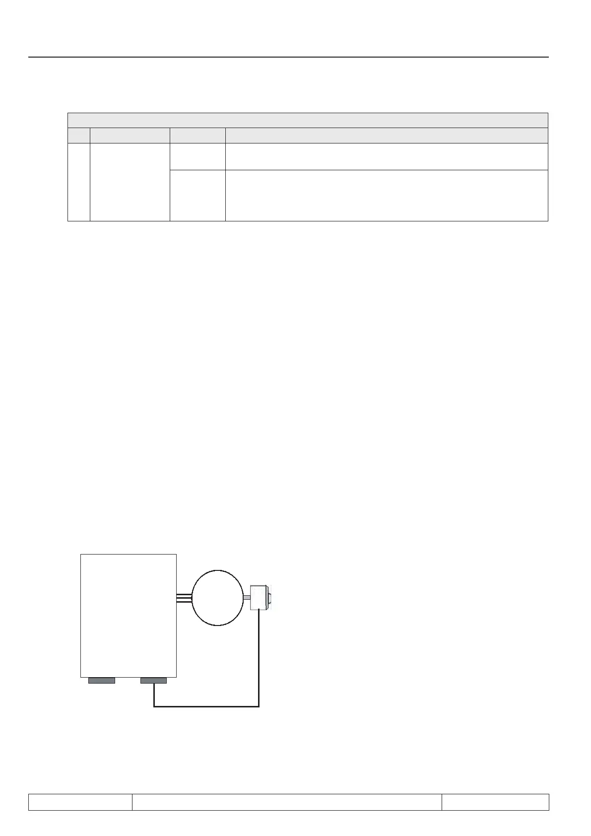
KEB COMBIVERT
F5A-S
or
F5A-S
X3B
Encoder
channel 2
X3A
Encoder
channel 1
M
3~
Example:
Let an incremental encoder with 2500 increments be
connected to encoder channel 1.
The motor shall travel 5.5 revolutions
Revolution in increments:
cS.01 = PS.01 = 0: Channel 1
Ec.04 = EC.05 = 1000 default value
Ec.01 = 2500 increments per revolution
Ec.07 = 2: 4-fold evaluation
→ 2500 x 2
2
x 5.5 = 55000 increments

 Loading...

