Torque display and -limiting
© KEB, 2012-10 COMBIVERT F5-A, -E, -H Page 7.8 - 3
7
7.8 Torque display and -limiting
Several factors limit the maximally available torque of a drive: in the base speed range, the current available
from the inverter, and in the eld weakening range, additionally, the voltage that limits the breakdown torque of
the motor. Torque limit e.g. to protect the mechanics is also required for some applications.
7.8.1 Maximum voltage controller, voltage limit
The inverter always requires a voltage control reserve to adjust the current. The maximum voltage controller
limits the output voltage if the output voltage is too high (higher dS.10 "Umax modulation limit"). The maximum
voltage controller is activated by the input of values 8 or 24 under point „maximum voltage controller“ of para-
meter dS.04 "ux/rotor adaption mode".
The controller is switched off at value 0 or 16.
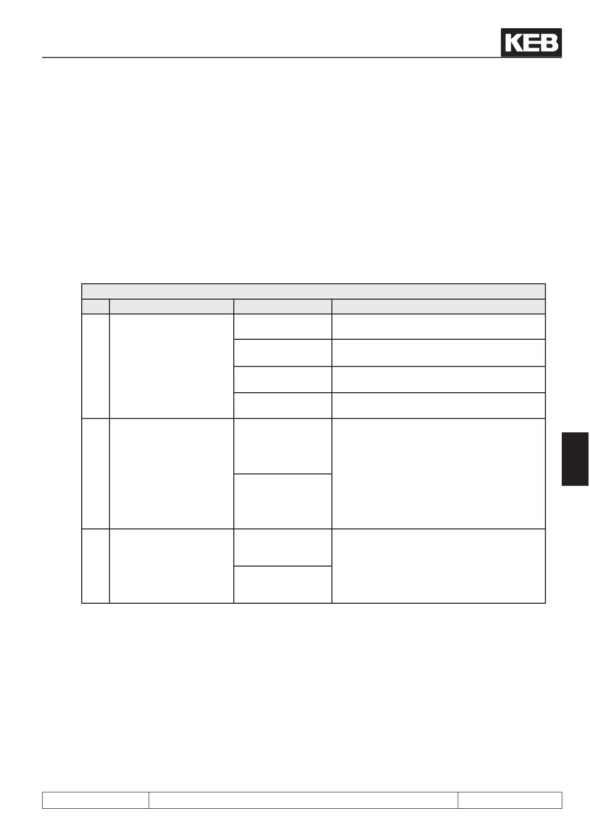
dS.04:Flux / rotor adaption mode
Bit Meaning Value Explanation
3, 4
Maximum voltage control-
ler
0: off, max. 110% controller off, max. modulation factor=110%
16: off, max. 100%
controller on,
max. modulation factor = ds.10 + 2%
16: off, max. 100% controller off, max. modulation factor=100%
24: on, max. 100% controller on, max. modulation factor=100%
10 Umax pos. difference limit
0: off
The negative difference of the maximum vol-
tage controller is limited to max. positive. Thus
the control characteristic is calm down.
Example:
maximum modulation factor = 100%
ref. modulation factor = 97%
limit = 100% – 97% = +/-3%
1024: on
11
Umax Stopp udCtrl in limi-
tation
0: off
If the current controller (isd) is in voltage limita-
tion, only positive differences are accepted in
the maximum voltage controller. The maximum
voltage controller can not integrate itself to ne-
gative and increase the current setpoint.
2048: on
The voltage range for which a modulation factor > 100% is needed is designated as overmodulation range.
The voltages in this area are no longer sinusoidal, which causes distortions in the phase currents, turbulent
speed estimation in encoderless operation and a worse torque accuracy.
A better output voltage is contrary to these disadvantages.
Overmodulation is not allowed with selection "max. 100%" (value 16 and 24). This adjustment should be se-
lected if the drive shall be operated in a mode with motor model (with or without speed feedback).
For the selection "max. 110%" (value 0 or 8), the available voltage increases due to exploitation of the non-
sinusoidal overmodulation range.
Value 0 should not be used because there are important negative effects.
The negative effects are minimized at value 8 by limiting the overmodulation range to „Umax modulation
limit“dS.10 + 2%. i.e. the maximum modulation factor is 105%, if dS.10 = 103% is selected. This limitation is
only valid for the overmodulation range.
The values 0 and 8 should only be used after careful testing.

 Loading...

