Page 7.5 - 20 COMBIVERT F5-A, -E, -H © KEB, 2012-10
Motor data and controller adjustments of the asynchronous motor
Main inductance (ASM) / EMC (SM) with rotation (dr.48 = 6)
It is necessary for the identication of the main inductance that the motor accelerates to the speed for maximum
torque (dr.17). The speed controller must be parameterised reasonable (select small Ki), the drive may not
vibrate during the identication.
The motor must be able to rotate in no-load operation. After the main inductance has been identied, the drive
stops automatically.
There is a special ramp "motor identication ramp time" (dr.49) for identication. This ramp applies for accele-
ration at the beginning and deceleration at the end of the identication.
Dead time detection (dr.48 = 9...13)
The dead time detection only works as single identication if the stator resistance is correct preset.
The measured dead time-values can be read out via In.39 and In.40.
The calibrated dead time compensation characteristics are in force if uF.18 = 3 is set.
7.5.2.3.2 Motor identicationerrorstatedr.66
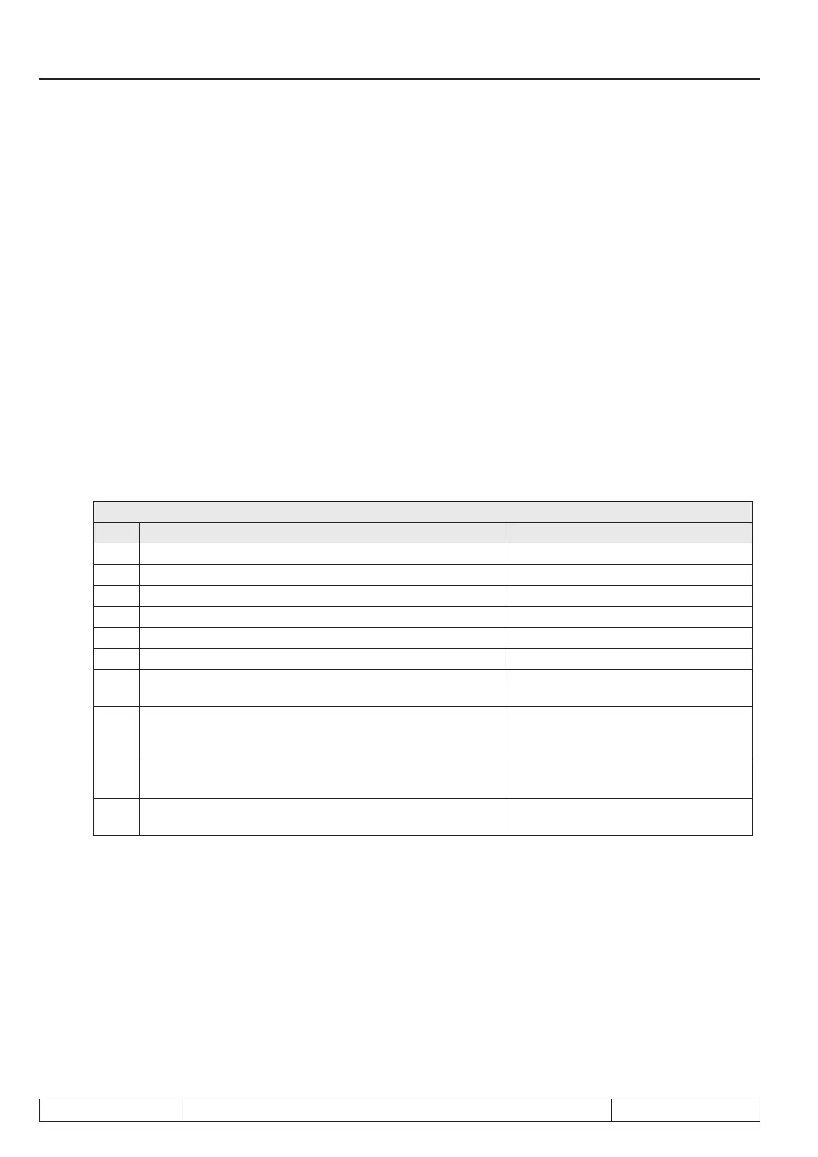
In error case parameter "motor identication error code" (dr.66) displays the reason for this error:
dr.66 Motoridenticationerrorstate
Value Description Notice
0 no error
1 Stator resistance Rs not within permissible range 0.001…250 Ohm
2 Rotor resistance Rr not within permissible range 0.001…250 Ohm
3 Leakage-/ winding inductance within permissible range 0.01…655.35 mH
4 Main inductance not within permissible range 0.1…3276.7 mH
5 DASM mag. current (dr.13) not within permissible range 0.25…0.75 rated motor current
6
Switching frequency changeover Occurs if the inverter exceeds the ra-
ting limit during the motor identication.
7
Rotor resistance measurement phase shifting not within
permissible range
The phase angle between current and
voltage is > 65 ° at smallest measuring
frequency and < 10 °at the largest.
8
Stator resistance measuring or dead time has reached
100% modulation
The modulation factor has reached
100%.
9
Frequency at Ls/L measurement not within permissible
range

 Loading...

