7.12.5 Contouring control mode
7.12.5.1 Contouring control mode / premises
For the contouring control mode, the bus-synchronous operation must be activated. Bus-synchronous operati-
on means that a control sends telegrams in a constant time pattern and that all connected inverters synchronise
to this pattern. This allows angular-synchronous and multi-axis operation, respectively.
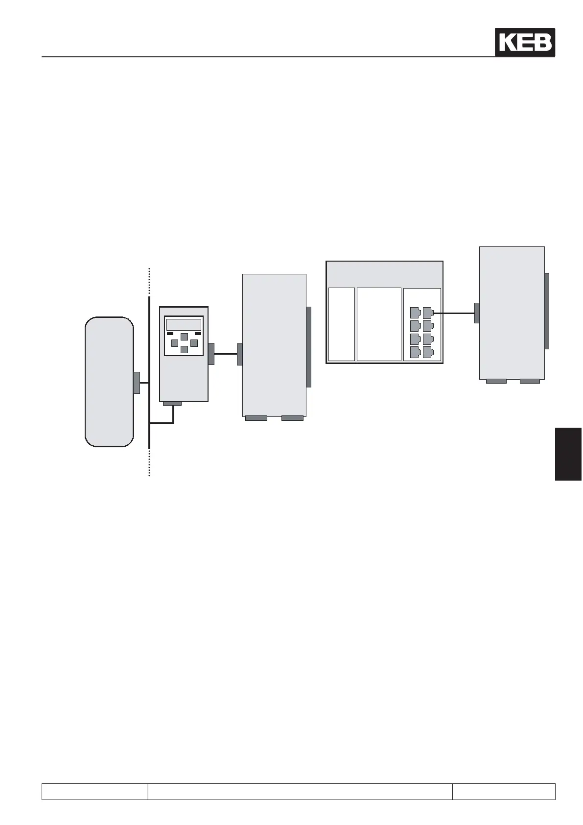
To implement the bus-synchronous operation, one requires either a fast eldbus system with the associated
KEB-operator or a fast control supporting the HSP5-protocol (e.g., a drive control COMBICONTROL C5).
The following bus systems are supported: CAN, SERCOS, EtherCAT, Powerlink, HSP5.
Fieldbus
(e.g. CAN, SERCOS,
EtherCat, Powerlink)
Customer
control
KEB
Operator
HSP5
Bus
KEB inverter
F5A-S
or
F5A-M
X3B
Encoder
channel 2
X3A
Encoder
channel 1
COMBICONTROL
C5
digital
I/O
optional
eldbus
interface
RS232
Parametrisation
Ethernet
Parametrisation
Visualisation
Drive
interface
KEB inver-
ter
F5A-S
or
F5A-M
X3B
Encoder
channel 2
X3A
Encoder
channel 1
How the bus-synchronous operation is realised and initialised depends on the fieldbus system used and must
be looked up in the instructions for the corresponding operator (CAN-operator, SERCOS operator, etc.).
The inverter enters the mode "bus-synchronous operation" if a value unequal to zero is set in parameter Sy.08
"bus synchronisation time" .
Note: As soon as the control sends cyclic telegrams in the pattern set in Sy.08, the bit 9 "HSP5 bus synchro-
nous" is set in the status word (Sy.51). The synchronous communication can be monitored with this bit. The
control release may only be given if the assembly of the bus-synchronous operation is completed.
Posi- and synchronous operating
© KEB, 2012-10 COMBIVERT F5-A, -E, -H Page 7.12 - 77
7

 Loading...

