Digital in- and outputs
© KEB, 2012-10 COMBIVERT F5-A, -E, -H Page 7.3 - 21
7
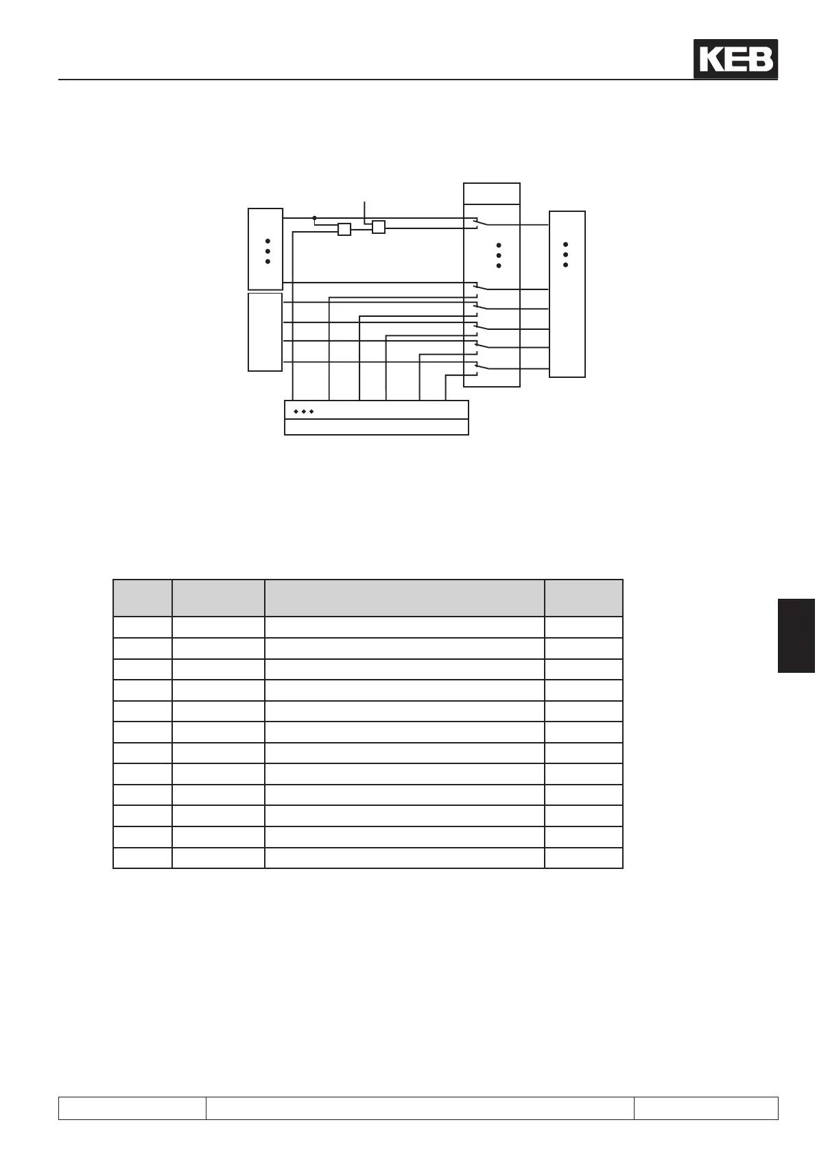
Fig. 7.3.3 Digital inputs controlled by software (di.01/di.02)
Terminal strip
1 128 256 512 1024 2048
ST
I4
IA
IB
IC
ID
ST
I4
IA
IB
IC
ID
di.2
1
128
256
512
1024
2048
di.1
&
&
Sy.50 Bit0 = 1
Înternal inputs
As shown in Fig. 7.3.3, it can be selected with di.01 , whether the inputs shall be switched from the terminal
strip (default) or by way of parameter di.02 . Both parameters are bit-coded, i.e. according to following table, the
appropriate value for the input is to be entered. In the case of several inputs the sum is to be formed.
(Exception: Control release must always be bridged at the terminal strip).
Table terminal state
Bit
-No.
Decimal va-
lue
Input Terminal
0 1 ST (prog. input „control release/reset“) X2A.16
1 2 RST (prog. input „reset“) X2A.17
2 4 F (prog. input „forward“) X2A.14
3 8 R (prog. input „reverse“) X2A.15
4 16 I1 (prog. input 1) X2A.10
5 32 I2 (prog. input 2) X2A.11
6 64 I3 (prog. input 3) X2A.12
7 128 I4 (prog. input 4) X2A.13
8 256 IA (internal input A) no
9 512 IB (internal input B) no
10 1024 IC (internal input C) no
11 2048 ID (internal input D) no
Example: ST, F and IB are controlled, indicated value = 1+4+512 = 517
7.3.4 Input terminal state (ru.21), internal input state (ru.22)
The terminal state (ru.21) displays the logical level at the input terminals. It is unimportant, whether the inputs
are internally active or not. If a terminal is controlled, the appropriate decimal value according to table "terminal
state" is output. If several terminals are active, then the sum of the decimal values is output.
The internal input state (ru.22) displays the logical state of the digital inputs internally set for further processing.
If an input is set, the appropriate decimal value according to table 7.3.1 is output. If several inputs are set, then
the sum of the decimal values is output.

 Loading...

