Page 7.2 - 10 COMBIVERT F5-A, -E, -H © KEB, 2012-10
Analog in- and outputs
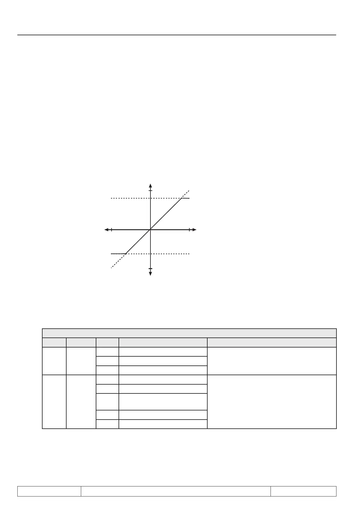
7.2.7 Lower- and upper limit (An.08, An.09, An.18, An.19, An.28, An.29)
These parameters serve for limiting of the analog signals after the amplier stage. All parameters are adju-
stable in the range of -400...400 %. Since no mutual locking exists, it is to be ensured, that the lower limit is
adjusted smaller than the upper limit.
An.08 AN1 lower limit
An.09 AN1 upper limit
An.18 AN2 lower limit
An.19 AN2 upper limit
An.28 AN3 lower limit
An.29 AN3 upper limit
Fig. 7.2.7 Limiting of the analog signal
400%
400%
-400%
-400%
An.9 / An.19 / An.29
An.8 / An.18 / An.28
7.2.8 Selection REFinput / AUX function (An.30)
Assignment of the analog inputs:
An.30: Sel. REF input/ AUX function
Bit Function Value Description Explanation
0...2
selection
REF
Input
0 AN1 input (ru.28)
Selection of the analog channel, which serves
as REF input
1 AN2 input (ru.30)
2 AN3 input (ru.32)
3...5
AUX
mode
0 Aux = source 1
Selection of the calculation of the AUX input
value (addition, multiplication or absolute-va-
lue generation)
8 Aux = source 1 + source 2
16
Aux = source 1 x (100% + sour-
ce 2)
24 Aux = source 1 x source 2
32 Aux = source 1 absolute

 Loading...

