Page 7.11 - 6 COMBIVERT F5-A, -E, -H © KEB, 2012-10
Speed measurement
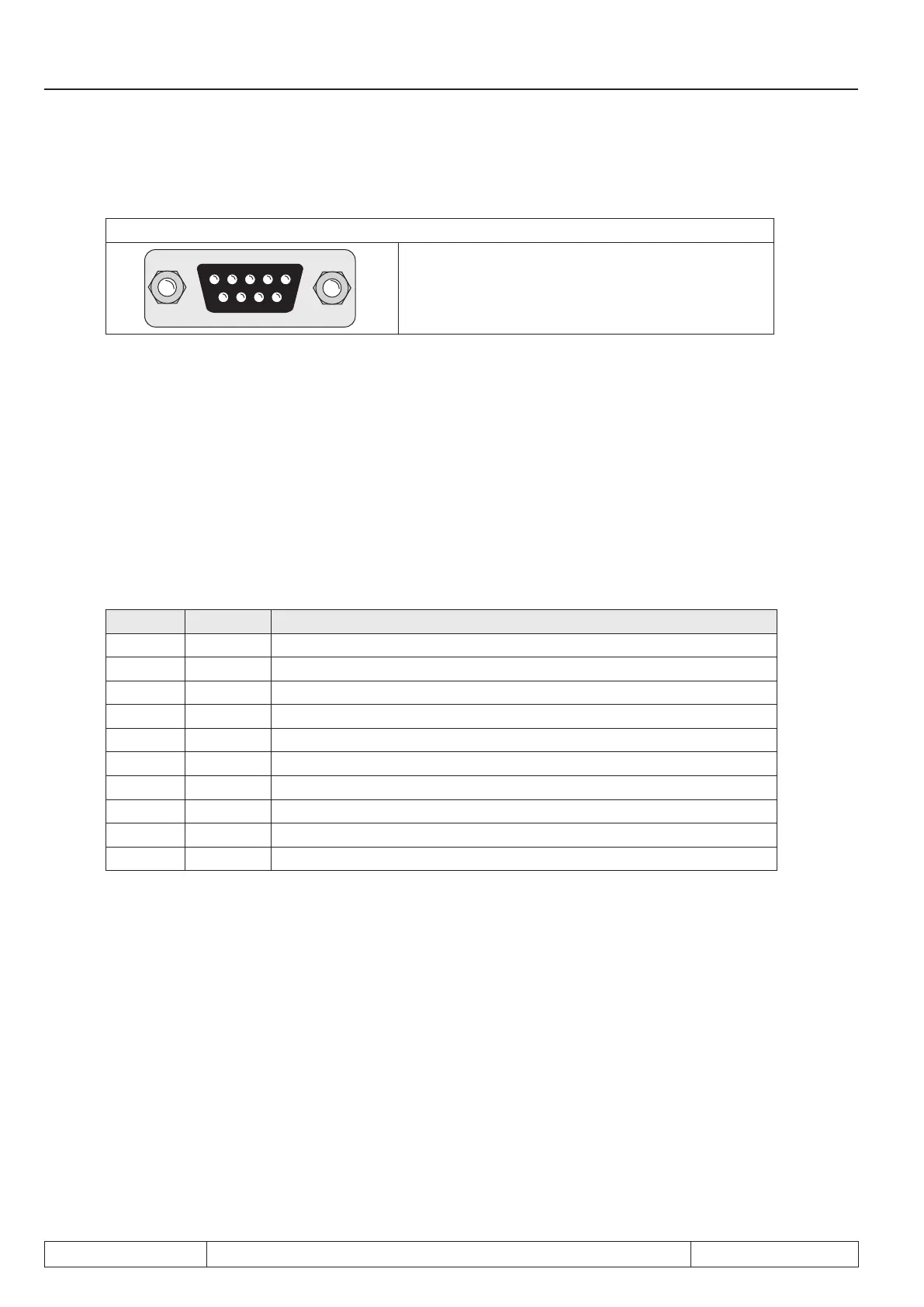
7.11.3 Encoder interface channel 2 (X3B)
Fig. 7.11.3 Encoder interface channel 2 (X3B)
54321
9876
Only when the inverter is switched off and the
voltage supply is disconnected may the plug be
pulled out or plugged in !
Channel 2 can be equipped with different interfaces. To avoid the connection of a wrong encoder, the installed
interface is indicated in ec.10.
Denition of the interface (Ec.10)
Channel 2 can be equipped with different interfaces. To avoid the connection of a wrong encoder, the installed
interface is indicated in ec.10.
7.11.3.1 Incremental encoder input
In synchronous operation the second incremental encoder serves as input of the master drive. A second posi-
tion encoder can be connected for positioning operation.
Signal X3B Description
U
var
5 Supply voltage for encoder (see 7.11.2)
+5,2V 4 Supply voltage for encoder (see 7.11.2)
0 V 9 Reference potential
A 1 Signal input A
_
A 6 Signal input A inverted
B 2 Signal input B
_
B 7 Signal input B inverted
n 3 Reference marking input N
_
N 8 Reference marking input N inverted
Shield housing shielding
The signal inputs of the second encoder interface support only rectangular signals.
Following
specications apply to the encoder interface 2 (X3B):
- Limiting frequency of input f
G
= 300 kHz
- internal terminating resistor R
t
= 150 Ω
-
2…5 V High level at rectangular signals

 Loading...

