Digital in- and outputs
© KEB, 2012-10 COMBIVERT F5-A, -E, -H Page 7.3 - 25
7
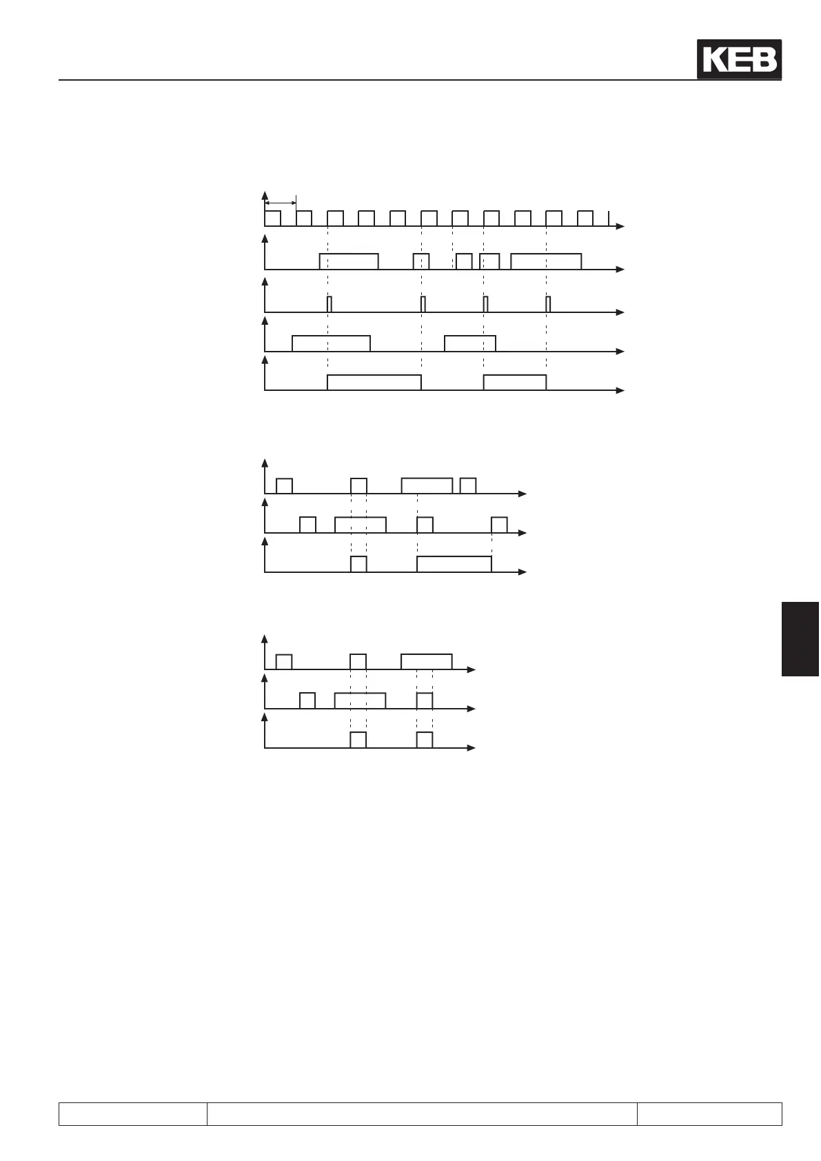
Fig. 7.3.8.a Edge active strobe (di.07 = 0)
Scanning grid
(ac-
ceptance upon rising
edge)
t
t
t
t
t
1ms
Strobe input
Resulting
Strobe signal
Signal at
terminals
Input status
Fig. 7.3.8.b Static strobe mode 1 (di.07 = 1)
input signal
t
t
t
Strobe signal
Input status
Fig. 6.3.8.c Static strobe mode 2 (di.07 = 2)
input signal
t
t
t
Strobe signal
Input status
7.3.10 Reset / input selection (di.09) and reset / input slope selction (di.10)
The reset input is dened with di.09 according table 7.3.1 . If the reset input shall react to a negative edge, one
or several of the reset inputs dened with di.09 can be switched to negative edge evaluation with di.1.

 Loading...

