Page 7.5 - 24 COMBIVERT F5-A, -E, -H © KEB, 2012-10
Motor data and controller adjustments of the asynchronous motor
fn = rated frequency
nn = rated speed
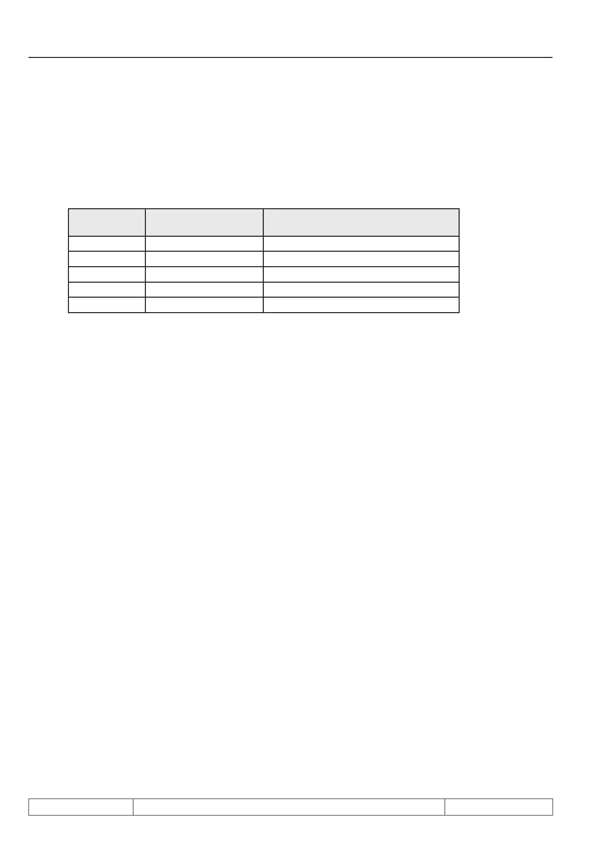
Selection of the rated switching frequency of the inverter:
The output frequency should not exceed 1/10 of the switching frequency.
Thus the following applies:
switching fre-
quency
max. output frequency output speed (for pole-pair number = 2)
2 kHz 200Hz 6000 rpm
4 kHz 400Hz 12000 rpm
8 kHz 800Hz 24000 rpm
12 kHz ---- ---
16 kHz 1600Hz 48000 rpm
Note: That a spindle e.g. with leakage inductance dr.07 = 1.4 mH and output frequency of 800 Hz (24000 rpm)
can be driven in practice also with 4kHz should not be considered for the dimensioning of the inverter.
Double modulation output:
An additional voltage vector can be output for 8 and16 kHz. The current controller is calculated only all 12 µs,
but the transformation angle is changed by 62.5 µs
(dS.18 bit 6 = on ).
Switching off the hardware current limit (HCL):
If the motor model is activated, HCL generally should be deactivated via uf.15 = 0 =off.
Identication of the equivalent circuit data:
• Main inductance:
There can be problems at measurement of the main inductance in lower speed range and when reaching
the target speed.
Lower speed range:
Measurement of the main inductance is started with a value for the inductance which is calculated from
the motor data. The lower speed range must be passed through speedy because the mode of calculation
can only be estimated and additionally the motor data of the manufacturers are problematically . For this
the additional ramp in dS.21 and dS.22 make sense.

 Loading...

