Page 7.5 - 26 COMBIVERT F5-A, -E, -H © KEB, 2012-10
Motor data and controller adjustments of the asynchronous motor
Switching off the dead time compensation at high output frequencies:
The dead time compensation is mandatory required up to 200 Hz, above 200 Hz it should be switched off. For
this a digital software output e.g. (do.04 = „27: actual speed > level“) level (LE.04 = 12000 rpm (ppz=1) with
hysterese LE.12 = 500 rpm and the input function uf.21 „dead time compensation off“ = 256 must be assigned
to the corresponding software input. With uf.25 in version 4.1 or 2.1 you can dene a time where the dead
time is soft switched off.
Load rejection of the current controller at dynamic procedure:
In order to unload the current controller at high output frequencies there are two possibilities:
a) Activate Pt1 element after speed controller
After the PI speed controller, a PT1 element can be activated via parameter cS.29.
A PT1 time of 2...8ms is recommended. Starting from version 4.1/2.1 parameter cS.29 is considered by the
mass-moment of inertia in the calculation for the controller parameter of the speed controller.
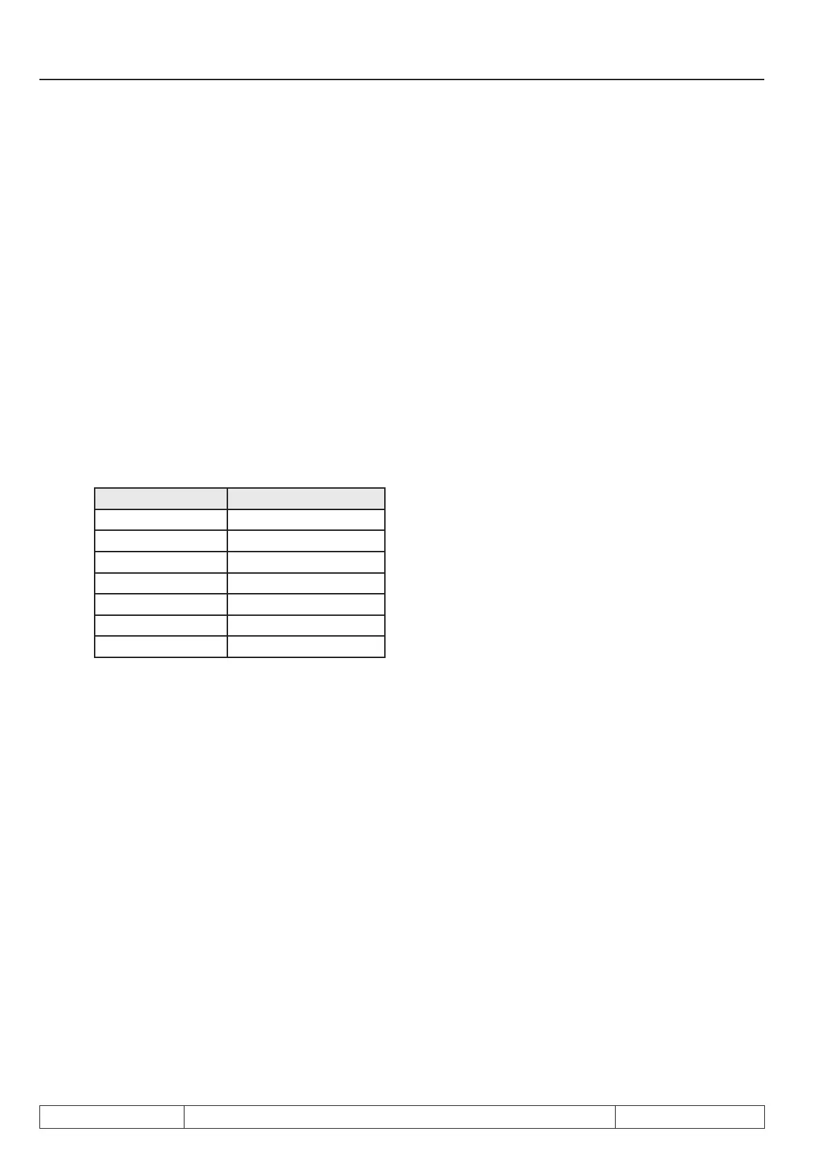
b) Ramp time and s-curve at deceleration:
Resolution mode Min. OP.30..31
Min. OP.34..35
4000 rpm 0.05 s
8000 rpm 0.1 s
16000 rpm 0.15 s
32000 rpm 0.25 s
64000 rpm 0.5 s
128000 rpm 1 s
Maximum current limiting and design of the inverter:
A maximum current can be preset in dr. 37 in order to protect the inverter against overcurrent error. dS.3 bit0
must be set additionally.
The distance to OC level is depending on:
• Current ripple dependent on the switching frequency (ft) and leakage inductance (Ls). A calculation of this
part is possible, but very extensive.
Rough formula : I Ripple = 46,4 / ft / Ls * kHz * mH *A (Ls in mH / ft in kHz)
• overshoot of the current controller, approx. 10% of the selected maximum current.
• the „300Hz“ reload voltage ripple (at 50Hz mains frequency) in the DC link. Serves for a superimposed
current oscillation in the output frequency (=output freq. - 300Hz). This part is depending on many factors
(size of DC capacitors (C), line supply impedance, leakage inductance of the motor (LS), active power (Pw).
Rough formula : IRipple_dc = Pw
2
/ C / Ls * 105 * µF * mH / kW
2
(Pw in kW / Ls in mH / C in µF
This part can be reduced by an input choke: 15% reserve to the OC level.

 Loading...

