Torque display and -limiting
© KEB, 2012-10 COMBIVERT F5-A, -E, -H Page 7.8 - 9
7
This value may not be fallen below for the following reason:
A potential error in the position sensing leads to the magnetising current creating a torque in the eld weake-
ning range. An error of 20° electrical causes an unwanted torque from the magnetising current of maximally:
Magnetizing current limit (dS.13)
—————————————————
DSM rated current (dr.32)
M
dS.13
= sin(20°) x x DSM rated torque (dr.27)
If this torque error cannot be compensated for due to the limiting characteristic, the drive becomes uncontrolla-
ble.
All other torque values must be selected higher accordingly.
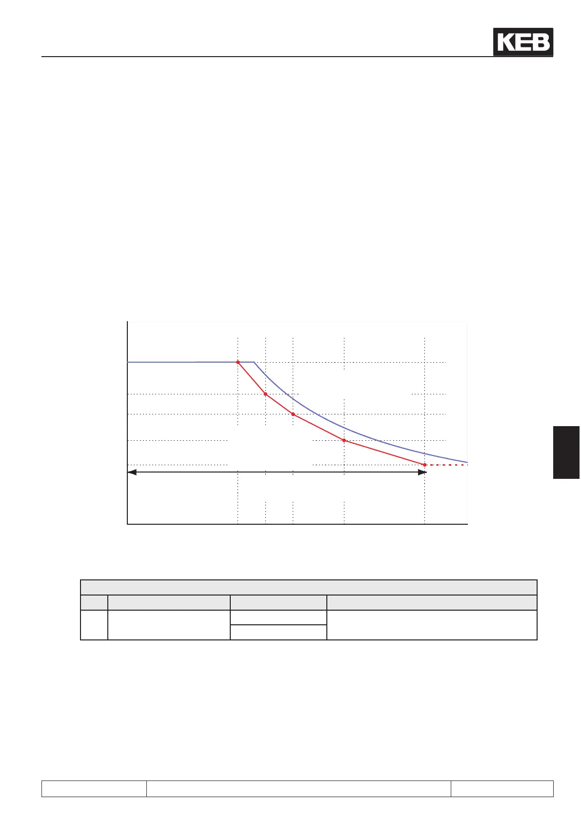
Parameters dr.33, 40, 42, 44, 46 contain the maximum torque for the speeds in dr.39, 41, 43, 45, 47. Linear
interpolation between these points.
Fig. 7.8.3.2.2 Limiting characteristic
measured limiting
characteristic
programmed limiting
characteristic in the
inverter
(with safety distance)
usable range of the
application
dr.39 dr.41 dr.43 dr.45 dr.47
dr.40
dr.42
dr.44
dr.46
dr.33
Torque
The limiting characteristic is activated via dS.03 bit 1.
dS.03: Current-/torque mode
Bit Meaning Value Explanation
1
Field weakening characte-
ristic
0: off
Activation of the limiting characteristic
(dened by dr.33, dr.40...47)
2: on

 Loading...

