Page 7.13 - 24 COMBIVERT F5-A, -E, -H © KEB, 2012-10
Protective functions
7.13.7.3 Ramp stop dependent on a digital input
With Pn.23 "ramp stop input selection", a digital input can be selected for triggering the ramp stop.This input is
only active if the stop is permitted in Pn.22 for the corresponding ramp.
7.13.8 Current limit constant run (stall function)
The Stall-function protects the frequency inverter against overload.
If the current (depending on the setting of the active or the apparent current in Pn.19) reaches the current limit
(Pn.20),
an attempt is made to lower the load by increasing / decreasing the output frequency.
Whether the output frequency must be increased or decreased depends on the torque characteristic of the
application. For a fan, e.g., the load factor increases with the speed, and the output frequency must be reduced
during overload. For a drilling machine, the load factor decreases with the speed, and the drive must therefore
be accelerated during overload.
When falling below the maximal constant current the inverter accelerates / decelerates again with the normal
ramp times.
The stall function is active until the original setpoint speed is reached.
This protection function is active only for F5A-M in open loop operation (cS.00 = off).
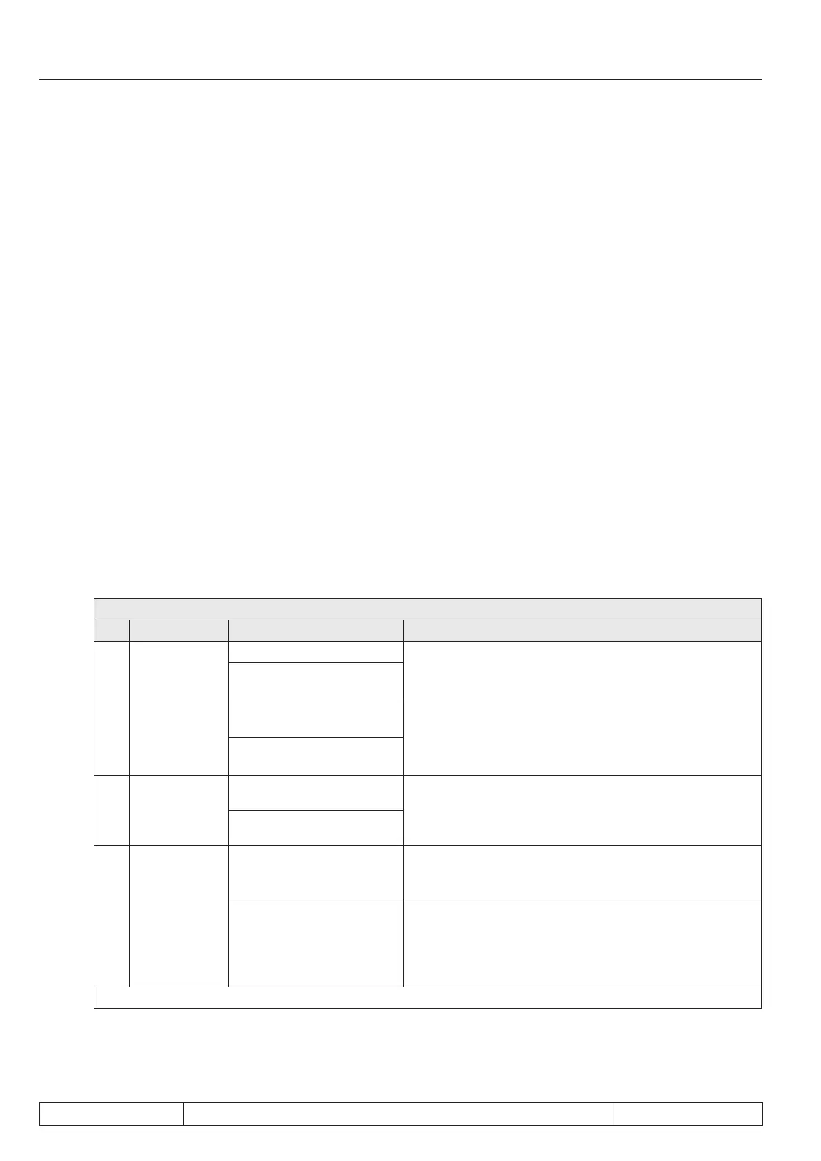
The basic mode of operation is determined with Pn.19:
Pn.19: Stall mode
Bit Meaning Value Explanation
0, 1
Frequency
limiting
0: oP.06, 07 or oP.10, 11
Final value to which it is possible to decelerate/accele-
rate.
1: 0 rpm respectively
oP.10, 11
2: oP.06, 07 respectively
oP.40, 41
3: 0 rpm respectively
oP.40, 41
2
Control
characteristic
in generator
operation
0: no change
With this bit, it is set whether the control direction (fre-
quency increase and decrease, respectively.) inverts in
generator operation.
4: Inversion
3 Ramp control
0: Ramp generator
The frequency is increased/decreased by way of the
ramp generator. The ramp time is preset by Pn.21.
8: Differential controller
The increase / decrease of the frequency is done by
a controller. The rate of change is dependent on the
difference current limit (Pn.20) - actual current. The time
constant of the controller is adjusted by Pn.21, the set-
point is adjusted by Pn.20.
further on next side

 Loading...

