Page 7.13 - 28 COMBIVERT F5-A, -E, -H © KEB, 2012-10
Protective functions
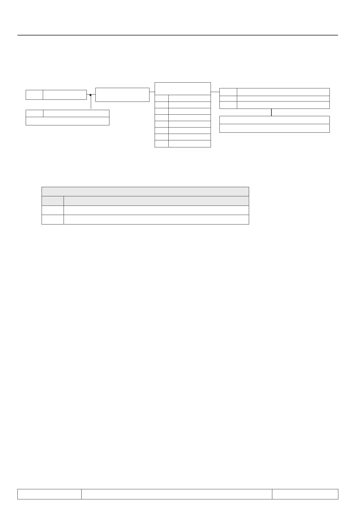
Fig. 7.13.8.a Motor protection mode
dr.11 Electronic motor protection
0 Separate cooling
1 Self-cooling
ru.15 Apparent current
dr.12 Motor protect. rated current
0.1…460.0 A
Fr.8 Motor set
assignment
0 Counter 0
1 Counter 1
2 Counter 2
3 Counter 3
4 Counter 4
5 Counter 5
6 Counter 6
7 Counter 7
Parameter set selection
see chapter 6.8
Pn.14 Motor protect. function response
0...6 (see Chapt. 6.7.6)
Motor protection mode (dr.11)
With this parameter, the cooling mode of the motor is set.
dr.11: Motor protection mode
Value Function
0 Separate cooling (default)
1 Self-cooling
Motor protection rated current (dr.12)
This parameter species for each set the rated current (= 100% utilisation) for the motor protective function.
The motor protection-load is calculated as follows:
inverter apparent current (ru.15)
——————————————
motorprot. rated current (dr.12)
Motor protection-load =
Warning OH2 stop. mode (Pn.14)

 Loading...

