Page 7.15 - 10 COMBIVERT F5-A, -E, -H © KEB, 2012-10
Special functions
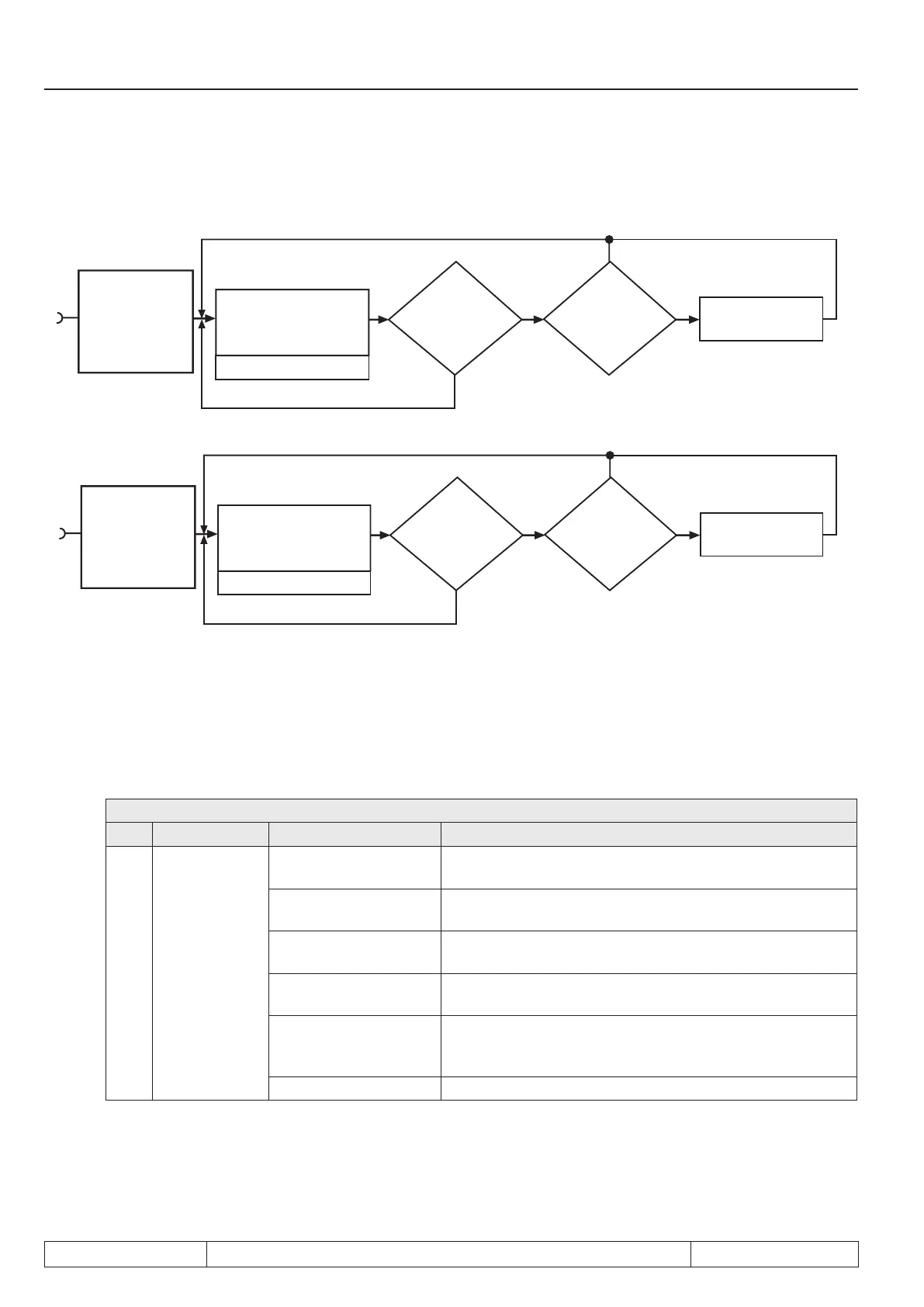
Fig. 7.15.4 Timer programming
Switching condition
37 „Timer 1 > Level A“
is being set!
Timer value > Level
LE.0...LE.7 ?
Is a
reset condition
of LE.20 or LE.19
fullled?
Timer counts up to maximum
value; down to 0, if a condition
of LE.18 is fullled or an input
of LE.17 is set
ru.43 timer 1 display
no
LE.21 Timer 1 /
Mode
no yes
yes
Resetting to zero
continues to count
Switching condition
38 „Timer 2 > Level A“
is being set!
Timer value > Level
LE.0...LE.7 ?
Is a
Is a reset condition
of LE.25 or LE.24
fullled?
Timer counts up to maximum
value; down to 0, if a condition
of LE.23 is fullled or an input
of LE.22 is set
ru.44 timer 2 display
no
LE.26 Timer 2 /
Mode
no yes
yes
Resetting to zero
continues to count
I3
I4
Timer mode (LE.21 / LE.26)
LE.21 and LE.26 determine the clock source and the counting direction of timer 1 and 2. Clock pulse source can
be the time counter in 0.01s or 0.01h grid, pulses from a digital input, or revolutions of the encoder on encoder
channel 1. The timer runs generally as long as a starting condition is active. After a reset the timer starts again
at zero. Following clock sources can be selected:
LE.21 / LE.26: Timer 1 / 2 mode
Bit Meaning Value Explanation
0...2
Selection clock
pulse source
0: 0,01s (internally
clock)
The timer value increases / decreases every 10 ms by 0.01
1: 0,01h (internally
clock)
The timer value increases / decreases every 36s by 0.01
2: every edge T1-I3 /
T2-I4
Each edge on I3 (for timer 1) or I4 (for timer 2) increases /
decreases the timer value by 0.01
3: positive edge T1-I3 /
T2-I4
A rising edge on I3 (for timer 1) or I4 (for timer 2) increases
/ decreases the timer value by 0.01
4: Rotation encoder 1
Each revolution (clockwise rotation and counter clockwise
rotation) of the encoder on channel 1 increases / decreases
the timer value by 0.01
5... 7: reserved

 Loading...

