Special functions
© KEB, 2012-10 COMBIVERT F5-A, -E, -H Page 7.15 - 15
7
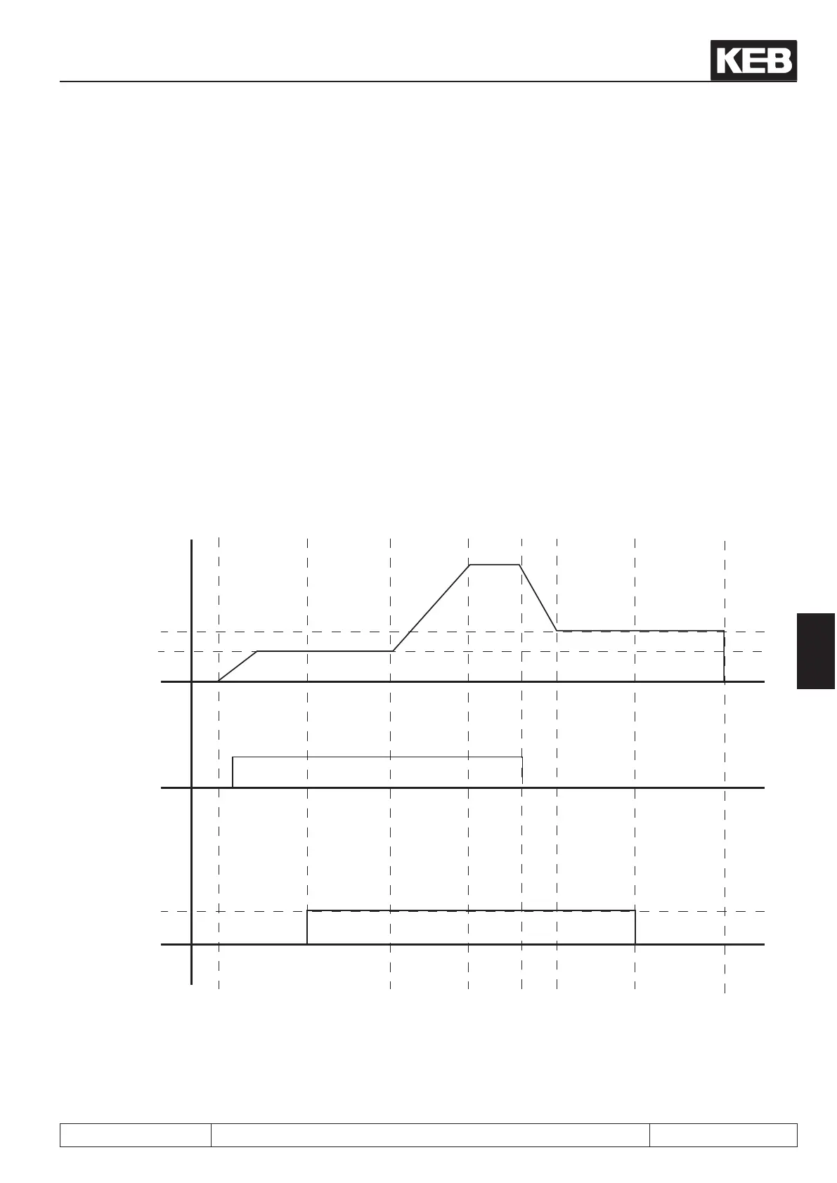
If the modulation is switched off, the break control output is immediately deactivated so that the brake closes.
In all other cases, the sequence is as follows:
• Pn.39: Brake delay time
After switching off the rotation setting, the drive runs to the stop speed Pn.41 (this parameter must contain
value 0 rpm for vector controlled drives) and waits there for the duration of the brake delay time.
• Pn.40: Brake closing time
Afterwards, the brake control output is deactivated and the brake takes over the load during the brake
closing time. The inverter remains during this time on stop speed Pn.41.
• Pn.38: Brake fadeout time
After expiration of the brake closing time (Pn.40), the fadeout time expires. During this time, the current is
lowered to 0. After expiration of the fadeout time, the modulation remains switched on for another 100 ms.
Thereby, the noise that can occur in the motor during a jolt-like shutdown of the current can be prevented.
After the current has been drained, the inverter changes into the status "70: standstill (Modulation off)"
(LS)
The following gure shows the sequence of the brake control without fadeout time. In vector controlled system,
the start- and the stop-value (Pn.37 / Pn.41) must be set to 0 rpm.
Figure 7.15.5.3 Brake control
LS
boff
facc
boff
fcon
boff
fcon
bon
fcon
bon
fcon
LSfacc facc fdec
Actual speed
opened
closed
Reference
(ru.01)
Stop value
(Pn.41)
Start value
(Pn.37)
Set direction
of rotation for
Inverter
state
brake
premagneti-
sing time
Pn.35
Brake re-
lease time
Pn.36
Brake delay
time
Pn.40
Brake clo-
sing time
Pn.40

 Loading...

