Performance Verification 1-15
6. Source the nominal full-scale resistance values for the 100
Ω
-10M
Ω
ranges summarized
in Table 1-6, and verify that the readings are within calculated limits.
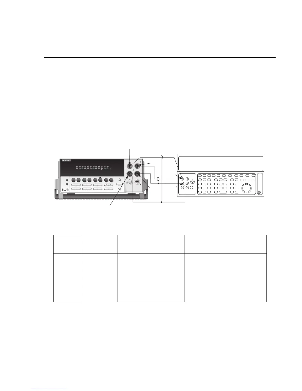
7. Connect the Model 2015 INPUT and SENSE jacks to the calibrator as shown in
Figure 1-6.
8. Disable external sense on the calibrator.
9. Set the Model 2015 for the 100M
Ω
range.
10. Source a nominal 100M
Ω
resistance value, and verify that the reading is within cal-
culated limits for the 100M
Ω
range.
Figure 1-6
Connections for resistance verification (100M
Ω
range)
Table 1-6
Limits for resistance verification
Ω
Range
Nominal
resistance
Nominal reading limits
(1 year, 18°C-28°C) Recalculated limits*
100
Ω
1k
Ω
10k
Ω
100kΩ
1MΩ
10MΩ
100MΩ
100Ω
1kΩ
10kΩ
100kΩ
1MΩ
10MΩ
100MΩ
99.9860 to 100.0140Ω
0.999890 to 1.000110kΩ
9.99890 to 10.00110kΩ
99.9890 to 100.0110kΩ
0.999890 to 1.000110MΩ
9.99590 to 10.00410MΩ
99.8470 to 100.1530MΩ
__________ to __________ Ω
__________ to __________ kΩ
__________ to __________ kΩ
__________ to __________ kΩ
__________ to __________ MΩ
__________ to __________ MΩ
__________ to __________ MΩ
* Calculate limits based on actual calibration resistance values and Model 2015 one-year accuracy
specifications. See Verification limits.
Output
LO
2015 THD MULTIMETER
RANGE
!
F
500V
PEAK
FRONT/REAR
3A 250V
AMPS
HI
INPUT
LO
SENSE
Ω 4 WIRE
INPUTS
350V
PEAK
1000V
PEAK
AUTO
SHIFT
LOCAL
POWER
RANGE
R
SHIFT
CH1REM
TALK
LSTN
SRQ
STAT
REL FILT
4W
BUFFER
MATH
REAR
SCAN
TIMER
STEP CH2 CH3 CH4 CH5 CH6 CH7 CH8 CH9 CH10
HOLD TRIG FAST MED SLOW AUTO ERR
EXIT ENTER
DIGITS RATE
RELFILTER
TRIG
EX TRIG
STORE
RECALL
SOURCE
MEAS
DCV
DCI
MATH
THD
dBm
ACV
ACI
Ω2 Ω4
FREQ
TEMP
dB
CONT
PERIOD TCOUPL
LIMITS ON/OFFDELAY
HOLD
SAVE SETUP
CONFIG HALT
TEST
RS232
GPIB
CAL
STEP SCAN
Model 2015
Input
LO
Input
HI
Resistance Calibrator
Note: Use shielded cables to minimize noise.
Disable calibrator external sense mode.
Sense HI
Sense LO
Output
HI
THD