1-14 Performance Verification
Verifying resistance
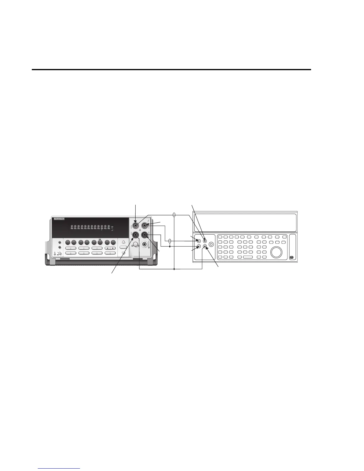
Check resistance by connecting accurate resistance values to the Model 2015 and verifying
that its resistance readings are within the specified limits.
CAUTION
Do not apply more than 1100V peak between INPUT HI and LO or more
than 350V peak between SENSE HI and LO, or instrument damage could
occur
.
Follow these steps to verify resistance accuracy:
1. Using shielded 4-wire connections, connect the Model 2015 INPUT and SENSE jacks
to the calibrator as shown in Figure 1-5.
Figure 1-5
Connections for resistance verification (100
Ω
-10M
Ω
ranges)
2. Set the calibrator for 4-wire resistance with external sense on.
3. Select the Model 2015 4-wire resistance function by pressing the
Ω
4 key, then choose
the SLOW integration rate with the RATE key.
4. Set the Model 2015 for the 100
Ω
range, and make sure the FILTER is on.
5. Recalculate reading limits based on actual calibrator resistance values.
Output
LO
2015 THD MULTIMETER
RANGE
!
F
500V
PEAK
FRONT/REAR
3A 250V
AMPS
HI
INPUT
LO
SENSE
Ω 4 WIRE
INPUTS
350V
PEAK
1000V
PEAK
AUTO
SHIFT
LOCAL
POWER
RANGE
R
SHIFT
CH1REM
TALK
LSTN
SRQ
STAT
REL FILT
4W
BUFFER
MATH
REAR
SCAN
TIMER
STEP CH2 CH3 CH4 CH5 CH6 CH7 CH8 CH9 CH10
HOLD TRIG FAST MED SLOW AUTO ERR
EXIT ENTER
DIGITS RATE
RELFILTER
TRIG
EX TRIG
STORE
RECALL
SOURCE
MEAS
DCV
DCI
MATH
THD
dBm
ACV
ACI
Ω2 Ω4
FREQ
TEMP
dB
CONT
PERIOD TCOUPL
LIMITS ON/OFFDELAY
HOLD
SAVE SETUP
CONFIG HALT
TEST
RS232
GPIB
CAL
STEP SCAN
Model 2015
Input
LO
Input
HI
Resistance Calibrator
Sense HI
Sense LO
Output
HI
Sense HI
Sense LO
Note: Use shielded low-thermal cables to
minimize noise. Enable or disable
calibrator external sense as indicated
in procedure.
THD