5-10 Disassembly
Changing trigger link lines
The Model 2015 uses two lines of the Trigger Link rear panel connector as External Trigger
(EXT TRIG) input and Voltmeter Complete (VMC) output. At the factory, line 1 is configured
as VMC and line 2 as EXT TRIG.
NOTE
Line 1, 3, or 5 of the Trigger Link can be configured as VMC, while line 2, 4, or 6 can
be configured as EXT TRIG.
You can change trigger link line configurations by moving the position of resistors inside the
unit. Perform the following steps to change trigger link lines:
WARNING
Make sure the instrument is disconnected from the power line and other
equipment before performing the following procedure.
1. Remove the cover from the instrument as explained in Case cover removal.
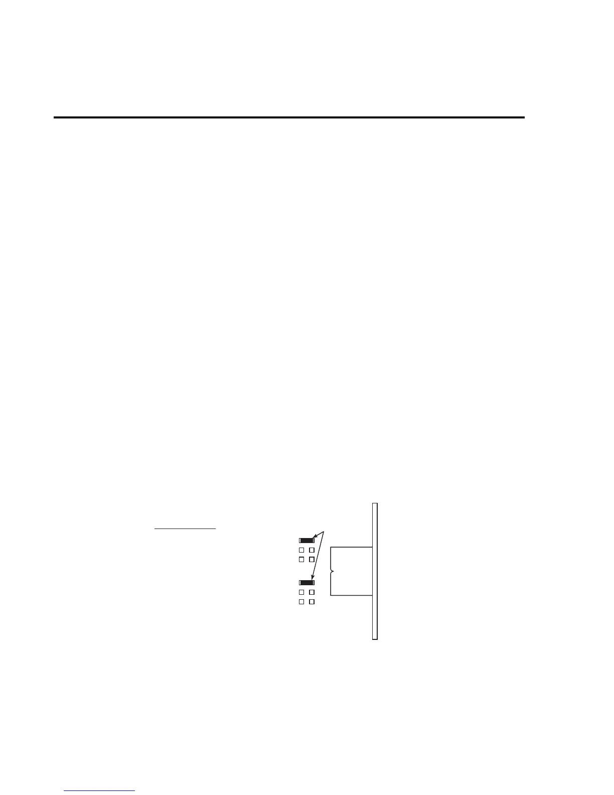
2. The resistors used to select the trigger link lines are located next to the Trigger Link
connector as shown in Figure 5-1. The “resistors” are actually solder beads that bridge
PC-board pads. If the factory default lines are selected, the solder beads will be located
at R270 (line 2, EXT TRIG) and R267 (line 1, VMC).
3. To change a trigger link line:
• Use a soldering iron and solder sucker to remove the appropriate solder bead.
• Using a solder with OA-based flux, apply a solder bead to the appropriate resistor
location.
• Replace the cover on the instrument.
Figure 5-1
Trigger link line connections
Trigger Link Lines
DMM Board
(View from top)
Line 1 = VMC (R267)
Line 2 = EXT TRIG (R270)
Line 3 = VMC (R266)
Line 4 = EXT TRIG (R268)
Line 5 = VMC (R265)
Line 6 = EXT TRIG (R269)
Trigger
Link
Connector
R270
R269
R268
R270
R269
R268
(Factory Default Configured)
Solder Bead
Rear Panel