2-18 Calibration
DC volts calibration
After front panel short and open steps, do the following:
1. Connect the calibrator to the Model 2015 as shown in Figure 2-2. Allow three minutes
for thermal equilibrium.
NOTE Although 4-wire connections are shown, the sense leads are connected and discon-
nected at various points in this procedure by turning calibrator external sense on or
off as appropriate. If your calibrator does not have provisions for turning external
sense on and off, disconnect the sense leads when external sensing is to be turned off,
and connect the sense leads when external sensing is to be turned on.
2. Perform the calibration steps summarized in Table 2-9. For each step:
• Set the calibrator to the indicated voltage, and make sure the unit is in operate. (Use
the recommended voltage if possible.)
• Send the indicated programming command. (Change the voltage parameter if you
are using a different calibration voltage.)
• Wait until the Model 2015 completes each step before continuing.
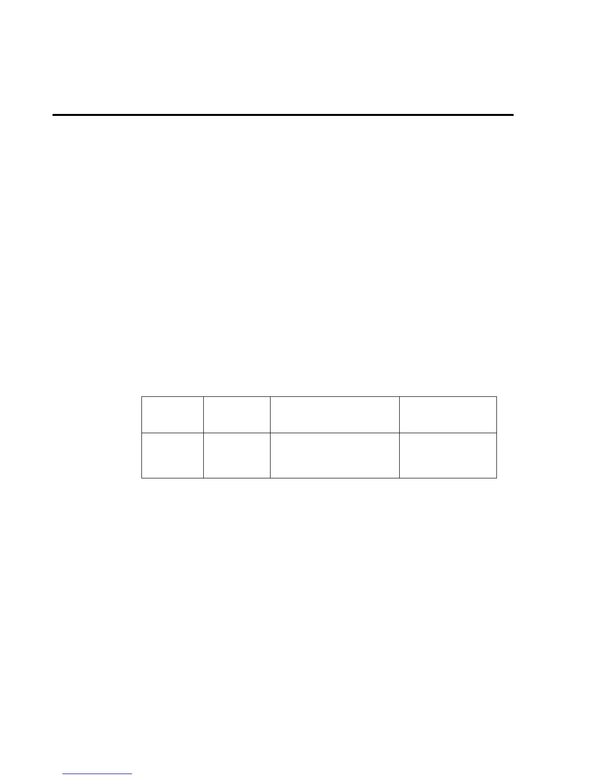
Table 2-9
DC voltage calibration programming steps
Calibration
step
Calibrator
voltage Calibration command* Parameter range
+10V
-10V
100V
+10.00000V
-10.00000V
100.0000V
:CAL:PROT:DC:STEP3 10
:CAL:PROT:DC:STEP4 10
:CAL:PROT:DC:STEP5 100
9 to 11
-9 to -11
90 to 110
* Use recommended value where possible. Change parameter accordingly if using a
different calibrator voltage.