Model 2750 Multimeter/Switch System User’s Manual Basic DMM Operation 3-19
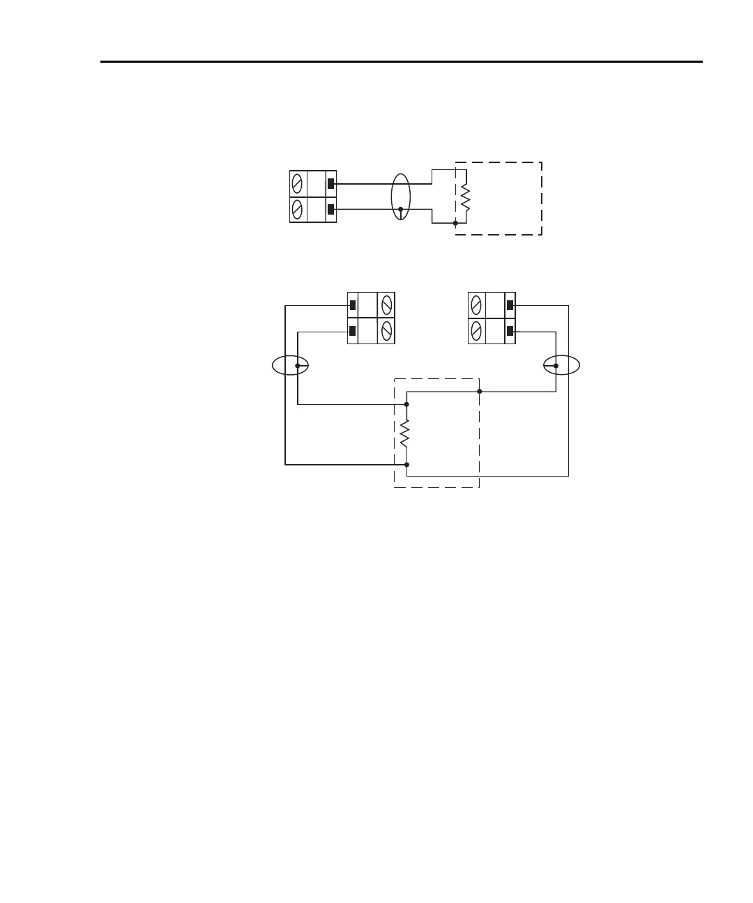
Figure 3-7
Ω2 and Ω4 connections for Model 7700 switching module
Standard resistance measurements
NOTE Make sure the INPUTS switch is in the correct position. To use front panel
inputs, it must be in the “F” (out) position. For switching modules, it must be in
the “R” (in) position.
Perform the following steps to measure resistance:
1. If a switching channel is presently closed (displayed), press OPEN to open it.
2. Select the ohms measurement function by pressing Ω2 or Ω4.
3. Use the RANGE
Δ and ∇ keys to select a measurement range consistent with the
expected resistance, or press AUTO to select autoranging (AUTO annunciator
turns on). Details on range are provided in Section 4.
4. Connect the resistance(s) to be measured.
H
L
CH 1-10
Model 7700
Switching
Module
H
L
CH 11-20
B. Ω4 Connections
INPUT
SENSE
Resistance
Under Test
Optional Shield
Shielded
Cable
Shielded
Cable
H
L
CH 1-20
Model 7700
Switching
Module
Resistance
Under Test
Shielded
Cable
Optional Shield
A. Ω2 Connections
Note: Source current flows from input
high (H) to input low (L).
2750-900-01.book Page 19 Wednesday, August 3, 2011 7:56 AM
 Loading...

