11-6 Status Structure Model 2750 Multimeter/Switch System User’s Manual
Reading registers
Any register in the status structure can be read by using the appropriate query (?) com-
mand. The following explains how to interpret the returned value (response message). The
actual query commands are covered later in this section (Table 11-2 through Table 11-5).
The response message for a register query will be a decimal value. This decimal value will
have to be converted to its binary equivalent. For example, decimal 19 in binary is 10011.
This binary value indicates that bits B0, B1, and B4 are set (1).
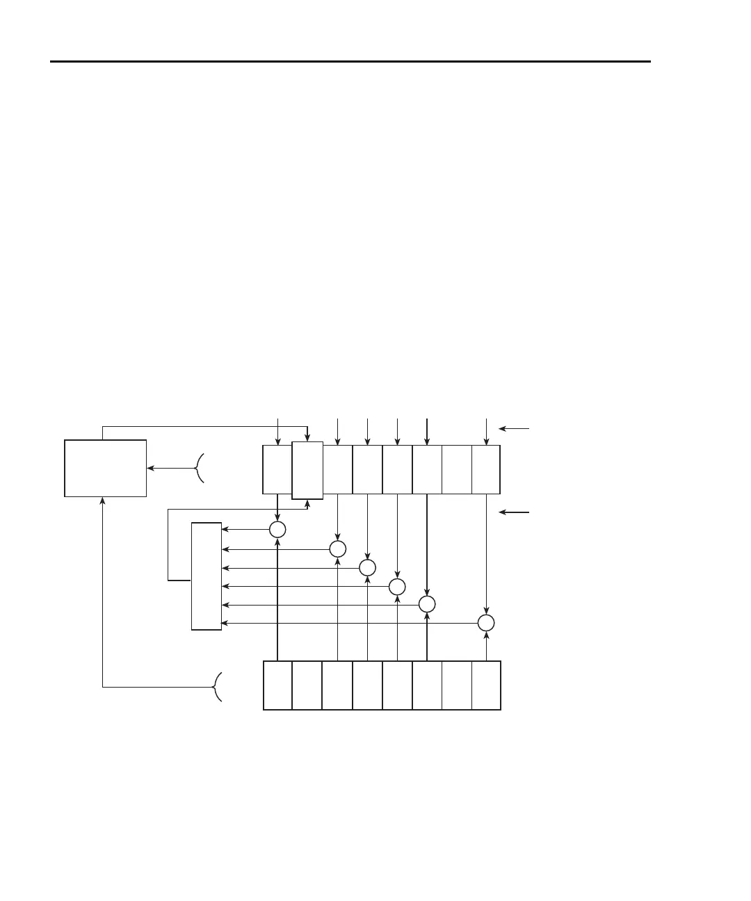
Status byte and service request (SRQ)
Service request is controlled by two 8-bit registers: the Status Byte Register and the Ser-
vice Request Enable Register. Figure 11-3 shows the structure of these registers.
Figure 11-3
Status byte and service request (SRQ)
OR
(B6)
Status Summary Message
Read by Serial Poll
Read by *STB?
OSB = Operation Summary Bit
MSS = Master Summary Status
RQS = Request for Service
ESB = Event Summary Bit
Mav = Message Available
Service Request
Enable Register
(B1)
__
____
&
*SRE
*SRE?
Status Byte
Register
Service
Request
Generation
*STB?
Serial Poll
RQS
(B6)
MSS
MSB
(B0)
EAV
(B2)
QSB
(B3)
MAV
(B4)
ESB
(B5)
OSB
(B7)
(B1)
MSB
(B0)
EAV
(B2)
QSB
(B3)
MAV
(B4)
ESB
(B5)
OSB
(B7)
QSB = Questionable Summary Bit
EAV = Error Available
MSB = Measurement Summary Bit
& = Logical AND
OR = Logical OR
&
&
&
&
&
2750-900-01.book Page 6 Wednesday, August 3, 2011 7:56 AM
 Loading...

