8-2 Triggering Model 2750 Multimeter/Switch System User’s Manual
Trigger model
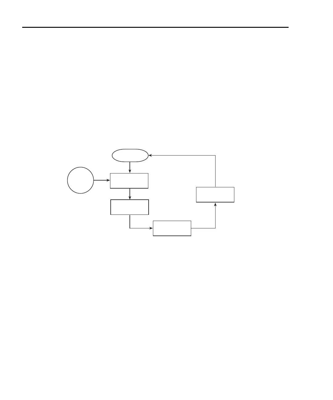
The flow chart in Figure 8-1 summarizes triggering as viewed from the front panel. It is
called a trigger model because it is modeled after the SCPI commands used to control
triggering.
NOTE For scanning, the trigger model has additional control blocks, such as a Timer.
These are described in Section 7 (Figure 7-1 and Figure 7-2). The complete trig-
ger model, which is based on bus operation, is shown and discussed later in this
section (“Remote programming — triggering,” page 8-12).
Figure 8-1
Front panel trigger model (without scanning)
Idle
When not scanning and in the continuous trigger mode (factory default setup), the instru-
ment will not stay in idle. Operation will continuously fall through the idle state and pro-
ceed to the Event Detection block of the trigger model. When in the one-shot trigger mode
(*RST default setup), the TRIG key must be pressed to take the instrument out of idle.
After each measurement, the instrument returns to idle and requires the TRIG key to be
pressed to continue. The FACT (factory) default setup or *RST default setup is selected
from the SHIFT > SETUP menu (see “Defaults and user setups,” page 1-19).
When scanning, the unit is considered idle at the end of a scan operation when the reading
for the last channel remains displayed. To restore triggers, press SHIFT and then HALT.
See Section 7 for details on scanning.
Idle
Control
Source
Immediate
External
Event
Detection
Output
Trigger
Auto Delay or
Manual Delay
Device Action
2750-900-01.book Page 2 Wednesday, August 3, 2011 7:56 AM
 Loading...

