D-2 Signal Processing Sequence and Data Flow Model 2750 Multimeter/Switch System User’s Manual
Signal processing sequence
Basic signal processing
The signal is applied to the multimeter input via front panel input terminals or a switching
module. When a channel is closed or scanned, the signal connected to that channel (or
channel-pair for 4-wire measurements) is connected to the input.
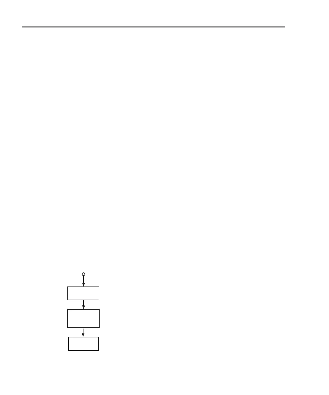
Figure D-1 is a flowchart that shows the basic processing sequence of an input signal.
With all the various features (filter, rel, math, ratio, channel average, buffer, etc.) of the
Model 2750 disabled, the input signal is conditioned and measured (A/D conversion pro-
cess). The reading is then displayed on the Model 2750.
Based on the selected measurement function and range, signal conditioning transforms the
input signal into a DC voltage that is applied to the A/D converter.
The A/D Conversion Process measures the DC signal voltage, and internal voltages that
correspond to offsets (zero) and amplifier gains. For TC temperature measurements using
a switching module that has an internal reference junction (i.e., Model 7700), the internal
temperature is also measured. These measurements are used in an algorithm to accurately
calculate the reading of the input signal. The voltage, current, resistance, frequency (or
period), or temperature reading is then displayed by the Model 2750.
NOTE The multiple measurement process used by the A/D converter is known as
autozeroing. It can be disabled to increase speed (only the signal is measured).
However, stability and accuracy will be affected over time and changes in tem-
perature.
Figure D-1
Basic signal processing
Display
Reading
A/D
Conversion
Process
Input Signal
Signal
Condtioning
2750-900-01.book Page 2 Wednesday, August 3, 2011 7:56 AM
 Loading...

