1-14 Getting Started Model 2750 Multimeter/Switch System User’s Manual
Power-up
Line power connection
Follow the procedure below to connect the Model 2750 to line power and turn on the
instrument.
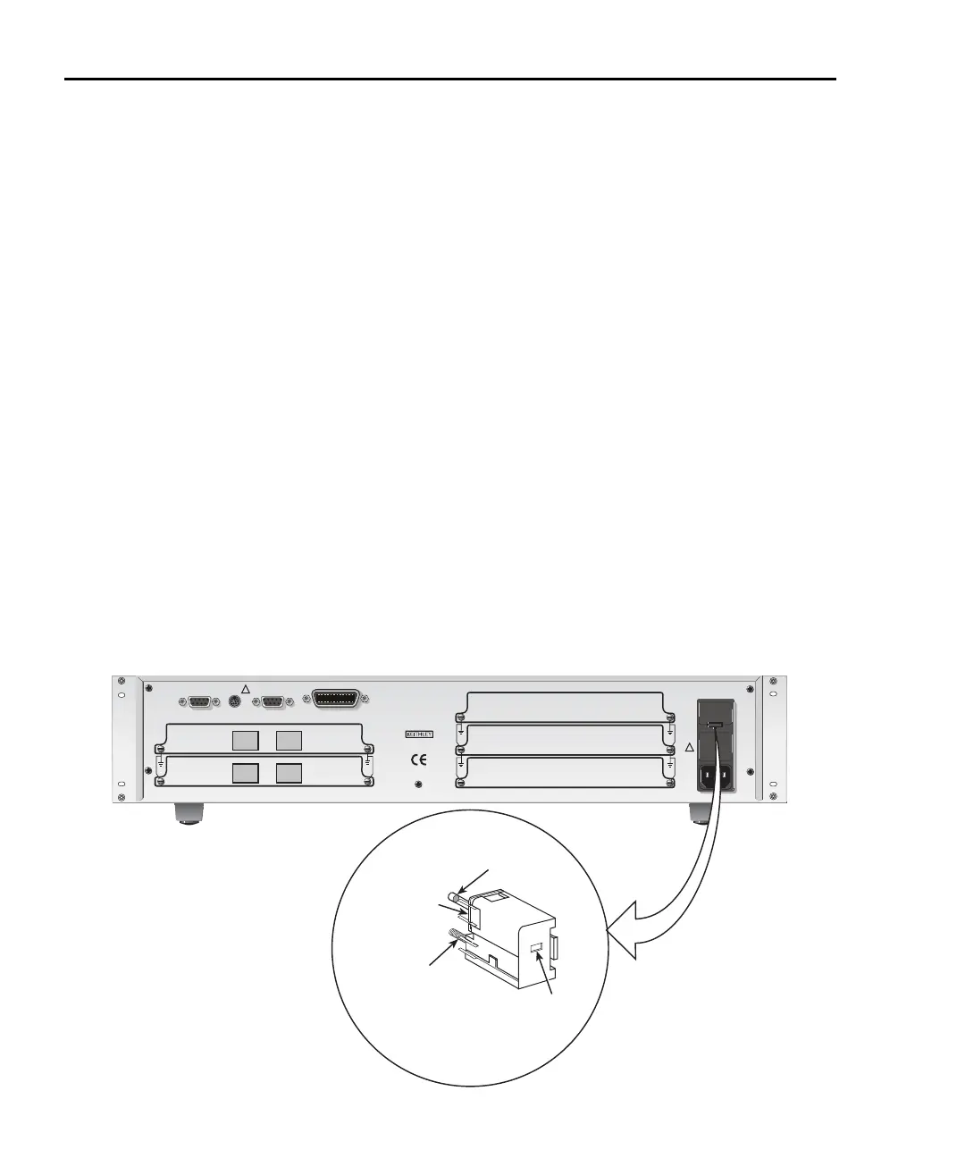
1. Check to see that the line voltage indicated in the window of the fuse holder assem-
bly (Figure 1-4) is correct for the operating voltage in your area. If not, refer to the
next procedure, “Setting line voltage and replacing fuse,” page 1-15.
CAUTION Operating the instrument on an incorrect line voltage may cause dam-
age to the instrument, possibly voiding the warranty.
2. Before plugging in the power cord, make sure that the front panel power switch is
in the off (O) position.
3. Connect the female end of the supplied power cord to the AC receptacle on the rear
panel. Connect the other end of the power cord to a grounded AC outlet.
WARNING The power cord supplied with the Model 2750 contains a separate
ground wire for use with grounded outlets. When proper connections
are made, instrument chassis is connected to power line ground
through the ground wire in the power cord. Failure to use a grounded
outlet may result in personal injury or death due to electric shock.
4. Turn on the instrument by pressing the front panel power switch to the on (I)
position.
Figure 1-4
Power module
Model 2750
IEEE-488
MADE IN
U.S.A.
!
CAT I
DIGITAL I/O TRIG. LINK
!
SLT
2
SLT
1
SLT
3
SLT
4
SLT
5
RS-232
KEITHLEY
SLOT COVER
KEITHLEY
SLOT COVER
KEITHLEY
SLOT COVER
Fuse
Spring
Window
Line Voltage
Selector
Fuse Holder Assembly
120
240
220
100
2750-900-01.book Page 14 Wednesday, August 3, 2011 7:56 AM
 Loading...

