2-8 Close/Open Switching Module Channels Model 2750 Multimeter/Switch System User’s Manual
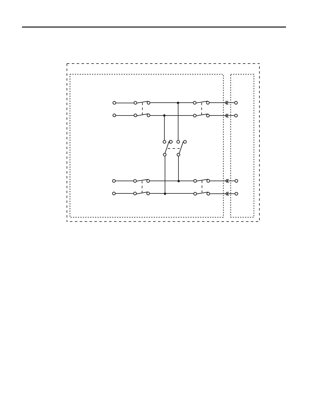
Figure 2-2
4-wire system channel connections to Model 2750 DMM
Controlling the system channel
When a measurement channel is closed, a previous system channel (and, for a 4-wire func-
tion, its paired channel) is first opened. The closed measurement channel becomes the sys-
tem channel. When a 4-wire function is selected, the paired channel for the system
channel also closes.
and keys
These front panel keys (Figure 2-3) can be used to select the next or previous measure-
ment channel as the system channel. If there are no measurement channels available, one
of the following messages will be briefly displayed when one of these keys is pressed:
NO SCAN CARD — This message indicates that there are no switching modules (or
pseudocards) installed. All five slots are empty.
NO MEAS CARD — This message indicates that none of the installed switching mod-
ules (or pseudocards) have measurement channels. For example, the Model 7705 switch-
ing module does not have any measurement channels. Those channels cannot be internally
connected to the DMM.
DMM
Model 7700 Switching Module
Model 2750
Slot 1
Close Channel 101
System Channel Operation:
(Closed Position
Shown
)
Channel 1
Relay
HI
LO
HI
LO
Input
Channel 25
Backplane
Isolation
Relay
Channel 1
Channel 11
Relay
HI
LO
HI
LO
Sense
Channel 24
Backplane
Isolation
Relay
Channel 11
Channel
23
2-Pole/4-Pole
Relay
2750-900-01.book Page 8 Wednesday, August 3, 2011 7:56 AM
 Loading...

