Model 2750 Multimeter/Switch System User’s Manual Close/Open Switching Module Channels 2-7
2-wire functions
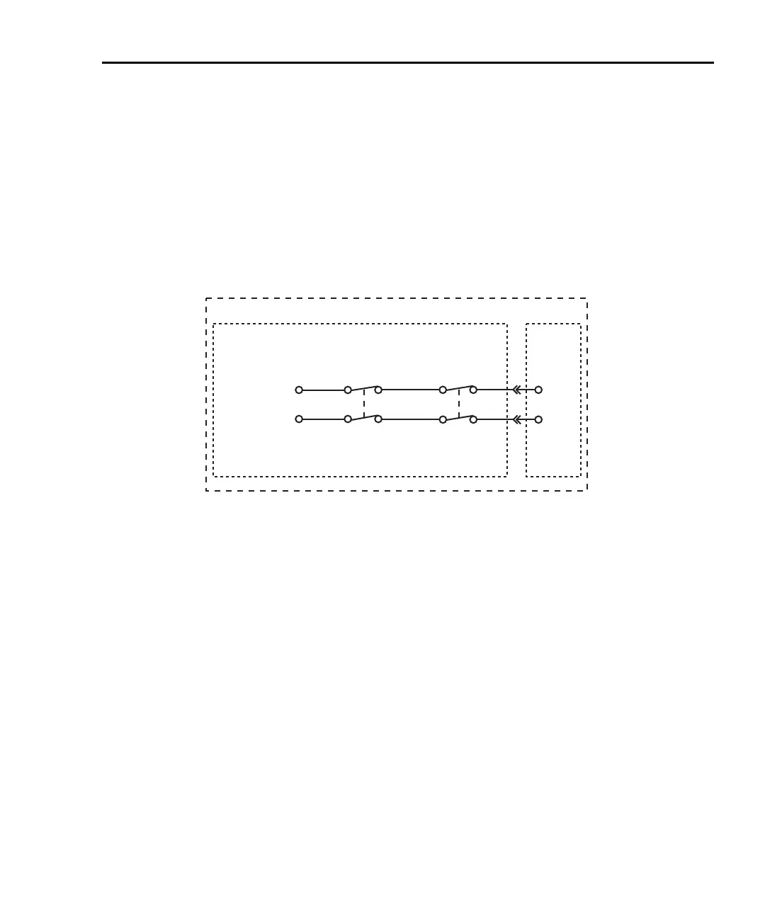
Figure 2-1 shows an example of how the system channel is connected to the DMM Input
of the Model 2750. Assume a Model 7700 switching module is installed in slot 1 of the
mainframe. When channel 101 is closed using the system channel close keys, both the
Channel 1 relay and the backplane isolation relay (Channel 25) closes to connect the chan-
nel to the DMM. The complete simplified schematic of the Model 7700 is provided in
Figure 2-12.
Figure 2-1
2-wire system channel connections to Model 2750 DMM
4-wire functions (paired channels)
A 4-wire function, such as Ω4, requires that another measurement channel be paired to the
system channel. For example, if the switching module has 20 measurement channels,
channels 1 through 10 can be used as the system channel, while channels 11 through 20
are used as the paired channel. For a switching module that has 20 measurement channels,
channel 1 is paired to channel 11, channel 2 is paired to channel 12, channel 3 is paired to
channel 13, and so on.
Figure 2-2 shows an example of system channel connections for a 4-wire function.
Assume a Model 7700 switching module is installed in slot 1 of the mainframe, and a 4-
wire function, such as Ω4, is selected. When channel 101 is closed using the system chan-
nel close keys, the Channel 1 relay and the input backplane isolation relay (Channel 25)
closes to connect the channel to DMM Input. Also, the Channel 11 relay and the sense
backplane isolation relay (Channel 24) closes to connect the paired channel to DMM
Sense. Also note in Figure 2-2 that the Channel 23 relay closes to isolate channel 1 from
channel 11.
The complete simplified schematic of Model 7700 is provided in Figure 2-12.
DMM
Model 7700 Switching Module
Model 2750
Slot 1
System Channel Operation:
Close Channel 101
Channel 1
Relay
HI
LO
HI
LO
Input
Channel 25
Backplane
Isolation
Relay
Channel 1
2750-900-01.book Page 7 Wednesday, August 3, 2011 7:56 AM
 Loading...

