S748-772 Instructions Manual | 9 Electrical Installation
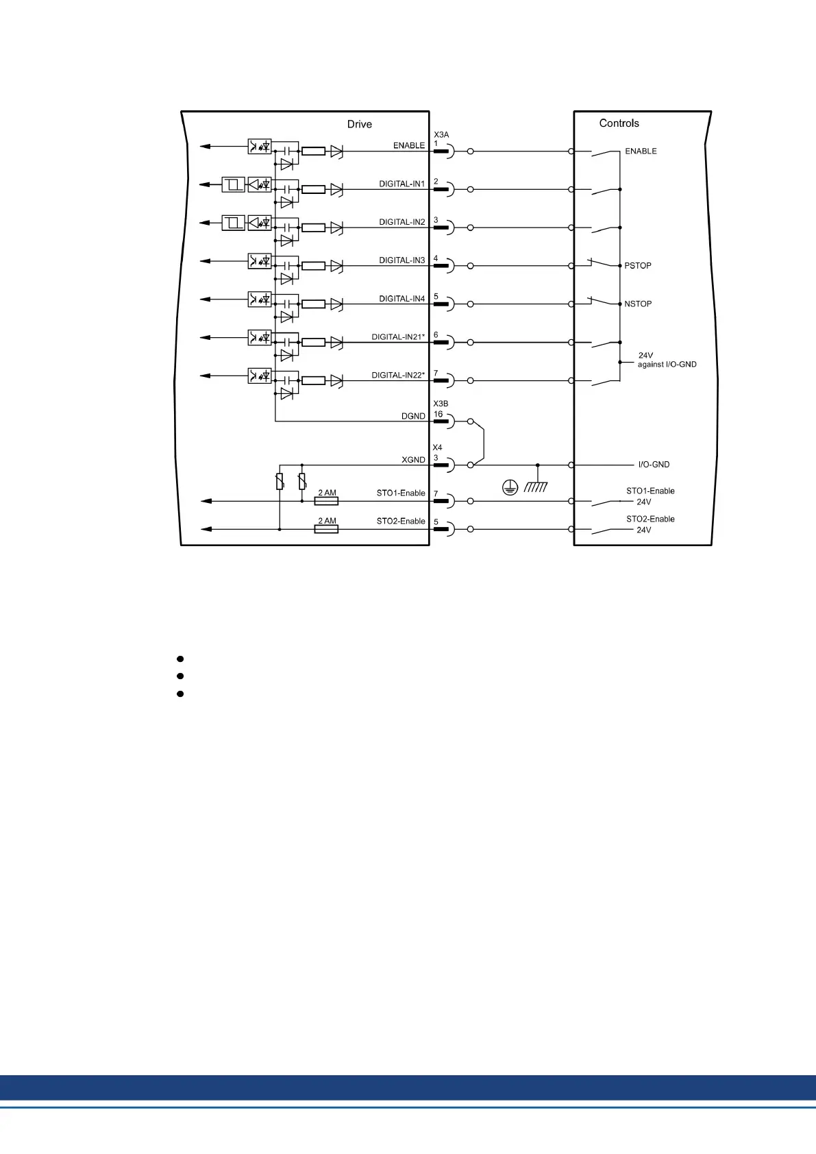
9.15.2 Digital Inputs (X3A, X3B, X4)
* * DIGITAL-IN 21 and 22 must be defined as inputs using the setup software (“Digital I/O” screen
page).
9.15.2.1 Connector X3A, X3B
Input ENABLE
PLC compatible (IEC 61131-2 type 1), floating, reference ground is DGND
High: 15...30 V / 2...15 mA , Low: -3...5 V / <1mA
Update rate: Software: 250 µs
The output stage of the servo amplifier is enabled by applying the ENABLE signal (Terminal
X3A/1, active high). Enable is possible only if inputs STOx-Enable have a 24 V signal (➜ #
41) ff). In the disabled state (low signal) the connected motor has no torque.
A software enable by means of the setup software is also required (AND link), although this
can also be permanently enabled (“Basic Setup” screen page of the DRIVEGUI.EXE setup
software).
Programmable digital inputs X3:
You can use the digital inputs X3A/2 to X3A/7 to initiate pre-programmed functions that are
stored in the servo amplifier. A list of these pre-programmed functions can be found on the
“Digital I/O” screen page of our setup software.
If an input was freshly assigned to a pre-programmed function, then the data set must be
saved in the EEPROM of the servo amplifier and a reset has to be carried out (with the amp-
lifier setup software for example).
100 Kollmorgen | kdn.kollmorgen.com | July 2019

 Loading...