7.9.9 Functional description
In case of use of the STO function the inputs STO1- Enable and STO2-Enable must be con-
nected to the exits of a security control or a safety relay, which meets at least to the require-
ments of the SIL CL2 according to IEC 62061 and PLd according to ISO 13849-1 (see
diagrams from (➜ # 47)).
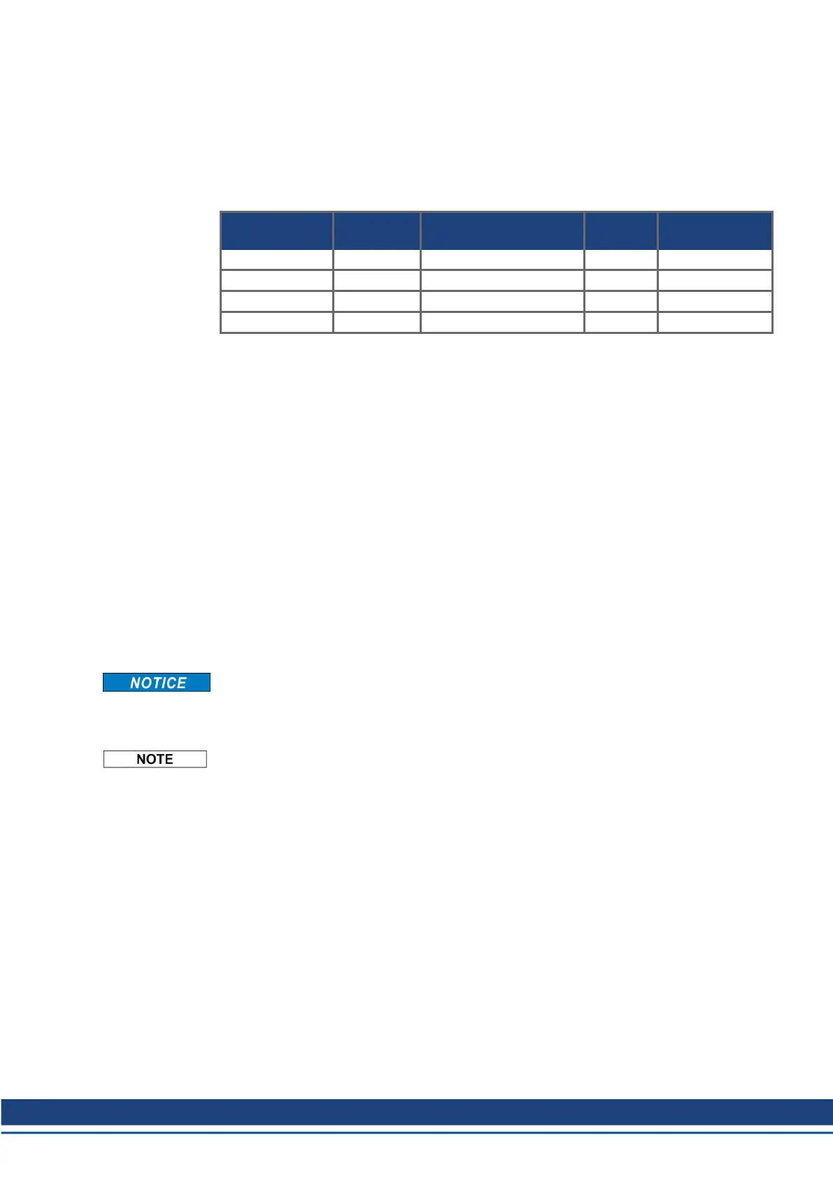
Possible states of the servo amplifier in connection with STO:
STO1-ENABLE
STO2-ENABLE
ENABLE Display Motor has
torque
SIL CL2 or 3
safety
0V 0V -S- no yes
0V +24V F27 no yes
+24V 0V normal status e.g. 06 no no
+24V +24V normal status e.g. E06 yes no
SIL2/PLd Single Channel Control
With the single-channel control of the STO (SIL2/PLd) safety function, both switch-off paths
STO1-Enable and STO2-Enable are switched by one output of a safety switching device
(e.g. safety relay), see example (➜ # 47).
In case of single channel usage of STO, erroneous engaging will not be recognized. There-
fore the output of the control must be supervised for possible malfunction.
SIL2/PLd Dual Channel Control
With the dual-channel control of the STO (SIL2/PLd) safety function, the switch-off paths
STO1-Enable and STO2-Enable are switched separately by two outputs of a safety switch-
ing device (e.g. safety relay), see example (➜ # 48).
SIL3/PLe Dual Channel Control
With the dual-channel control of the STO safety function, the switch-off paths STO1-Enable
and STO2-Enable are switched separately by two outputs of a safety control, see example
(➜ # 49).
To achieve PL e or SIL CL3, the safe switching of the pulse inhibitor must be tested peri-
odically by analyzing the feedback (status) signal from the safety control (➜ # 51).
When wiring the STO inputs within an enclosure it must be paid attention to the fact that the
used cables and the enclosure meet the requirements of IEC 60204-1.
If the wiring leads outside the demanded enclosure, the cables must be laid durably (firmly),
and protected from outside damage (➜ # 43).
If STO function is not needed in the application, then the inputs STO1-ENABLE and STO2-
ENABLE must be connected directly with +24VDC. STO is passed by now and cannot be
used. Now the servo amplifier is not a safety component referring to the EC Machine Dir-
ective.
S748-772 Instructions Manual | 7 Technical description
Kollmorgen | kdn.kollmorgen.com | July 2019 45

 Loading...