S748-772 Instructions Manual | 11 Expansions
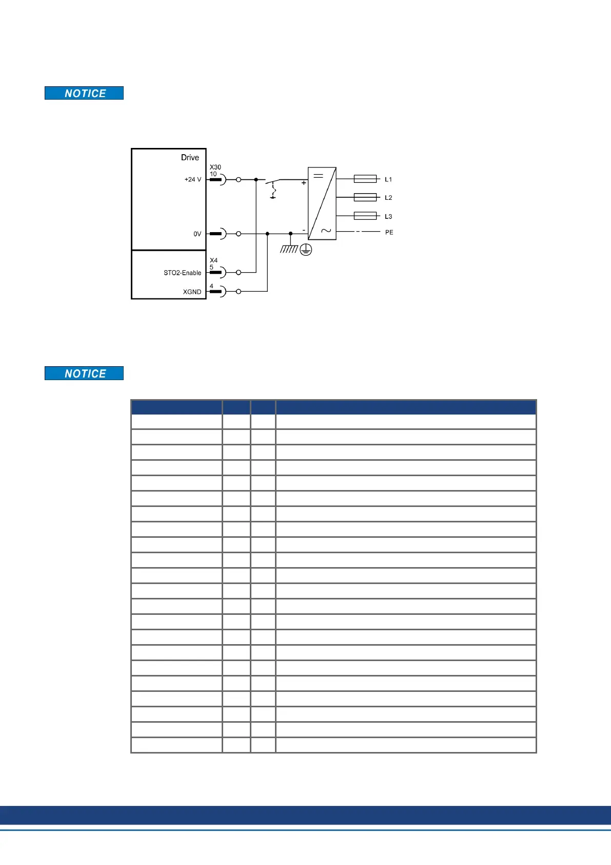
11.3.4.3 Wiring supply voltage 24 V for digital outputs
Input X4/5 "STO2-Enable" must be connected to +24V DC and must not be used as addi-
tional STO input!
Input STO1-Enable [X4/7] must
not be connected.
11.3.4.4 Safe inputs and outputs S2-2
Inputs X30/1 SS1_Activate and X30/20 Reset must always be connected. Only tested out-
puts from a safety control system may be connected to all inputs on X30.
X30 Pin I/O Description
SS1 Activate 1 I Activates function SS1
I0 2 I Programmable, activate safety function X
I1 3 I Programmable, activate safety function X
I2 4 I Programmable, activate safety function X
STO Acknowledge 5 O Status: STO activated
O0 6 O Programmable, status: safety function X activated
O1 7 O Programmable, status: safety function X activated
O2 8 O Programmable, status: safety function X activated
O3 9 O Programmable, status: safety function X activated
24V Supply 10 - 24V supply of digital outputs
n.c. 11 - n.c.
I3 12 I Programmable, activate safety function X
I4 13 I Programmable, activate safety function X
I5 14 I Programmable, activate safety function X
I6 15 I Programmable, activate safety function X
Ready 16 O Message "Safety card is ready to operate"
n.c. 17 O n.c.
n.c. 18 O n.c.
n.c. 19 O n.c.
Reset 20 I Input for Reset
0V Supply 21 - 0V supply of digital outputs
0V Supply 22 - 0V supply of digital outputs
154 Kollmorgen | kdn.kollmorgen.com | July 2019

 Loading...