7.4 LED display
A 3-character LED-Display indicates the status of the amplifier after switching on the 24 V
supply (➜ # 121). When the keys on the front panel are used, the parameter and function
numbers are shown, as well as the numbers for any errors and warnings that may occur (➜ #
123).
7.5 Grounding system
AGND - analog inputs, internal analog ground
DGND - 24V-IO, digital inputs and digital outputs, optically isolated.
GND - internal digital ground, encoder Emulation, RS232, CAN
XGND - 24V supply, STO Enable, ventilator
BRGND - 24V motor brake supply
7.6 Dynamic braking (brake circuit)
During braking with the aid of the motor, energy is fed back into the servo amplifier. This gen-
erated energy is dissipated as heat in the brake resistor. The brake resistor is switched in by
the brake circuit. The setup software can be used to adapt the brake circuit (thresholds)
according to the electrical supply voltage. Our customer service can help you with the cal-
culation of the brake power that is necessary for your system. A simple method is described
in the "KDN". A description of the interface can be found on page (➜ # 71).
Functional description:
1.- Individual amplifiers, not coupled through the DC bus link circuit (DC+, DC-)
When the energy fed back from the motor has an average or peak power that exceeds the pre-
set level for the brake power rating, then the servo amplifier generates the warning “n02 brake
power exceeded” and the brake circuit is switched off. The next internal check of the DC bus
link voltage (after a few milliseconds) detects an overvoltage and the output stage is
switched off, showing the error message “Overvoltage F02” (➜ # 123).
The BTB/RTO contact (terminals X3B/14,15) will be opened at the same time (➜ # 102).
2.- Several servo amplifiers coupled through the DC bus link (DC+, DC-)
Using the built-in brake circuit, several amplifiers of the same series can be operated off a
common DC bus link (observe (➜ # 70)), without requiring any additional measures. 90% of
the combined power of all amplifiers is always available for peak and continuous power.
The switch-off on overvoltage takes place as described under 1. (above) for the amplifier that
has the lowest switch-off threshold (resulting from tolerances).
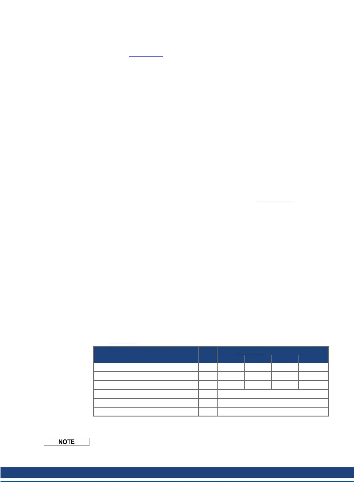
Technical data of the brake circuits depend on the amplifiers type and the mains voltage situ-
ation (VBUSBAL).
Technical Data VBUSBAL: Supply voltage
Rated data DIM 1:230 V 2:400 V 3:480 V 4*:480 V
Switch-on threshold of brake circuit V 400 720 840 790
Overvoltage F02 V 455 800 900 900
Pulse brake power kW 16 50 70 70
External brake resistor (RBe), S748 Ohm 15
External brake resistor (RBe), S772 Ohm 10
Continuous brake power (RBe) kW 8
* Kollmorgen recommends setting VBUSBAL=4 in case of 480 V mains supply, with this set-
ting the optimized calculation method is used.
Suitable external brake resistors can be found in our accessories manual.
S748-772 Instructions Manual | 7 Technical description
Kollmorgen | kdn.kollmorgen.com | July 2019 35

 Loading...