S748-772 Instructions Manual | 11 Expansions
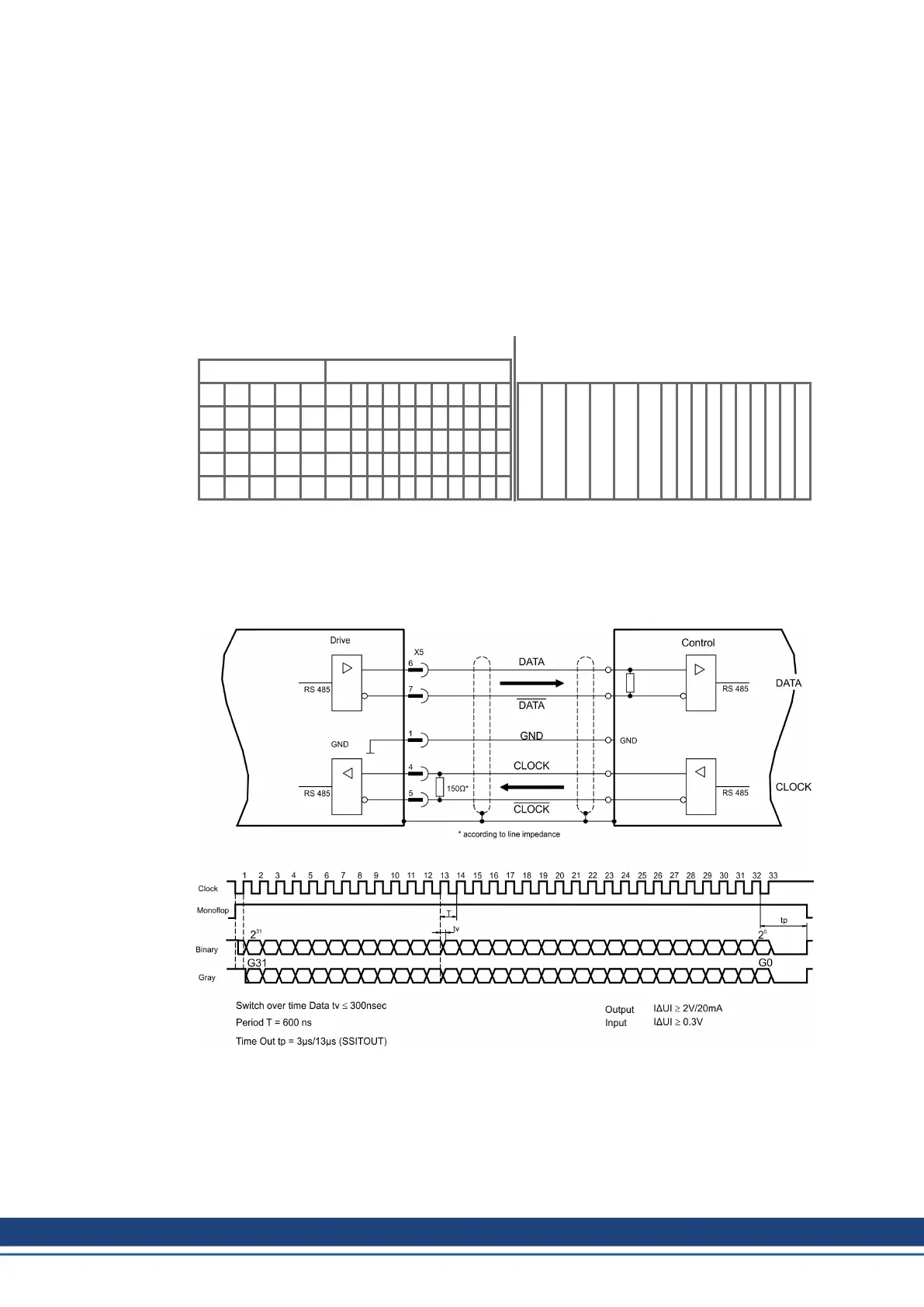
11.2.3.3.2 SSI encoder output (X5)
SSI interface (synchronous serial absolute-encoder emulation). Select encoder function SSI
(“Encoder Emulation” screen page, ENCMODE 2). The servo amplifier calculates the motor
shaft position from the cyclic-absolute signals of the resolver or encoder. From this inform-
ation a SSI date (Stegmann patent specification DE 3445617C2) is provided. Max 32 bits are
transferred. The leading data bit contains the number of revolutions and are selectable from
12 to 16 bits. The following max. 16 bits contain the resolution and are not variable.
Die führenden Datenbit bilden die Anzahl der Umdrehungen ab und sind wählbar von 12 bis
16 Bit. Die darauf folgenden max. 16 Bit bilden die Auflösung ab und sind nicht veränderbar.
The following table shows the allocation of the SSI date depending upon selected number of
revolutions:
Revolution Resolution (variable)
SSIREVOL
15 14 13 12 11 10 9 8 7 6 5 4 3 2 1 0
14 13 12 11 10 9 8 7 6 5 4 3 2 1 0
13 12 11 10 9 8 7 6 5 4 3 2 1 0
12 11 10 9 8 7 6 5 4 3 2 1 0
11 10 9 8 7 6 5 4 3 2 1 0
15 14 13 12 11 10 9 8 7 6 5 4 3 2 1 0
The signal sequence can be output in Gray code or in Binary (standard) code. The servo amp-
lifier can be adjusted to the clock frequency of your SSI-evaluation with the setup software.
The drivers operate off an internal supply voltage.
Connection and signals for the SSI interface:
Default count direction: UP when the motor shaft is rotating clockwise (view at shaft's end)
150 Kollmorgen | kdn.kollmorgen.com | July 2019

 Loading...