10.7.5 Digital inputs/outputs, connector X21A (SubD 15-pin, socket)
Inputs (In): 24V (20...28V), opto-isolated, one high-speed input (Pin 4)
Outputs (Out): 24V, opto-isolated, Darlington driver
Pinout connector X21A (SubD 15 pin)
Pin Type Description
1
In +24V Power supply
2
Out NODEALARM Indicates a problem with the node
3
Out OUT_01 Digital output
4
In IN_00 (fast) Capture input (fast)
5
In IN_04 Digital input
6
In IN_01 Digital input
7
In HOME Reference switch
8
In POSLIM Limit switch, positive direction
9
In GND Power supply
10
Out OUT_00 Digital output
11
Out OUT_02 Digital output
12
In IN_02 Digital input
13
In IN_03 Digital input
14
In NEGLIM Limit switch, negative direction
15
In NODEDISABLE Disables Node
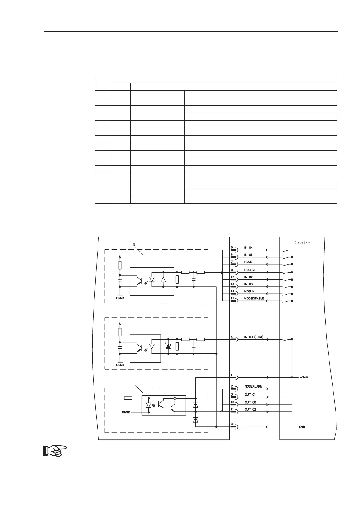
10.7.6 Connection diagram digital inputs/outputs, connector X21A
AGND and DGND (connector X3) must be joined together !
SERVOSTAR
®
640/670 Instructions Manual 109
Kollmorgen
12/2010 Expansion Cards
SERVOSTAR

 Loading...


