2LW/2LX
1-5-16
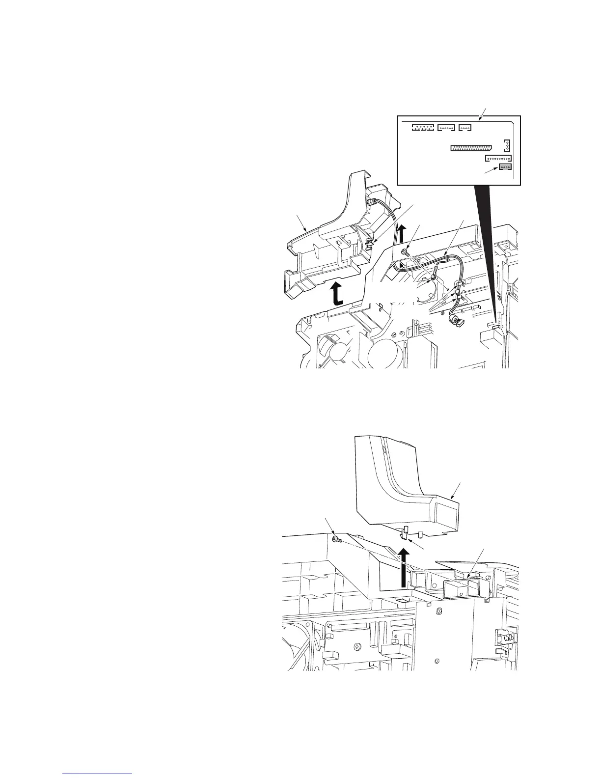
(3) Detaching and refitting the laser scanner unit
Procedure
1. Remove the right cover and left cover.
(See page 1-5-3)
2. Remove the document processor.
(See page 1-5-11)
3. Remove the scanner unit.
(See page 1-5-13)
4. Remove the connector from the main
PWB.
5. Remove the screw and grounding ter-
minal.
6. Release three clamps and then remove
the wires.
7. Unhook the hook and then remove the
right front upper cover.
Figure 1-5-22
8. Unhook the hook and then remove the
left front upper cover.
9. Remove the one screw on upper cover
rack.
Figure 1-5-23
YC3
Screw
Grounding
terminal
Main PWB
Right front
upper cover
Clamps
Wire
Connector
Hook
Screw
Left front
upper cover
Hook
Upper cover rack
 Loading...