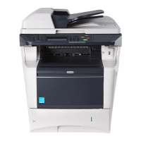
2LW/2LX
2-3-4
Connector Pin Signal I/O Voltage Description
YC5 1 OPSDO O 0/5 V DC (pulse) Serial communication data signal output
Connected to
connect-L
PWB
2 +24V2 I 24 V DC 24 V DC power from CPWB-L (via ILSW)
3 +24V2 I 24 V DC 24 V DC power from CPWB-L (via ILSW)
4 GND - - Ground
5 GND - - Ground
6 GND - - Ground
7 GND - - Ground
8 GND - - Ground
9 +24V1 I 24 V DC 24 V DC power from CPWB-L
10 +5V1 I 5 V DC 5 V DC power from CPWB-L
11 +5V1 I 5 V DC 5 V DC power from CPWB-L
12 +5V1 I 5 V DC 5 V DC power from CPWB-L
13 +5V2 O 5 V DC 5 V DC power to CPWB-L
YC7 1 GND - - Ground
Connected to
lift sensor
2 LIFTSEN I 0/5 V DC LS: On/Off
3 +5V2 O 5 V DC 5 V DC power to LS
YC9 1 WETCLK2 O 0/5 V DC (pulse) TEMS clock signal
Connected to
connect-R
PWB
I Analog TEMS detection voltage (humidity)
2 WETCLK1 O 0/5 V DC (pulse) TEMS clock signal
3 +5V1 O 5 V DC 5 V DC power to CPWB-R
4 AIRTEMP I Analog TEMS detection voltage (temperature)
5 RFANDRN O 0/12/24 V DC RFM: Full speed/Half speed/Off
6 +24V1 O 24 V DC 24 V DC power to CPWB-R
7 MPFDRN O 0/24 V DC MPSOL: On/Off
8 OUTB2 O 0/24 V DC (pulse) SBM drive control signal
9 OUTB1 O 0/24 V DC (pulse) SBM drive control signal
10 OUTA2 O 0/24 V DC (pulse) SBM drive control signal
11 OUTA1 O 0/24 V DC (pulse) SBM drive control signal
12 GND - - Ground
YC11 1 +24V4 O 24 V DC 24 V DC power to DRM
Connected to
drum motor
2 GND - - Ground
3 DMOTRDYN I 0/5 V DC DRM ready signal
4 DMOTCLK O 0/5 V DC (pulse) DRM clock signal
5 DMOTONN O 0/5 V DC DRM: On/Off
 Loading...


