2LW/2LX
2-3-5
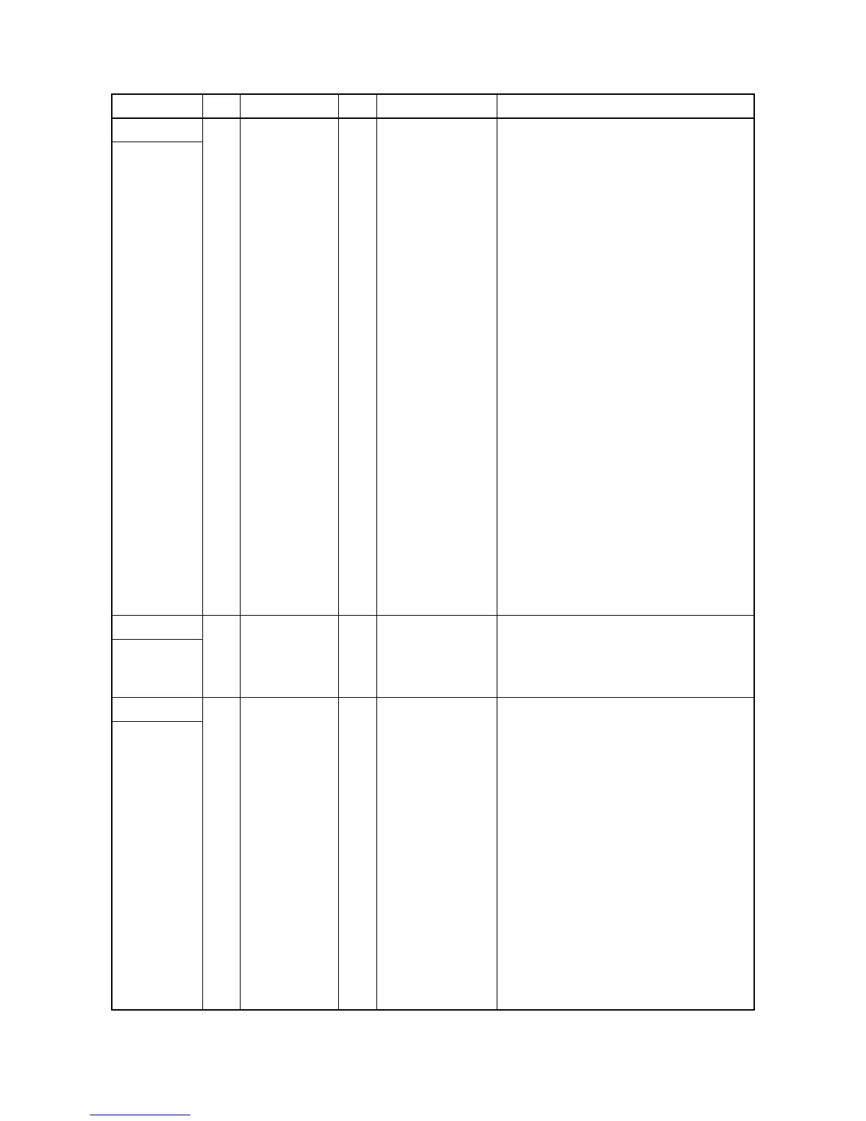
YC12 1 POLRDYN I 0/5 V DC PM ready signal
Connected to
main PWB
2 POLONN O 0/5 V DC PM: On/Off
3 OUTPEN O 0/5 V DC Laser output enable signal
4 PDMASKN O 0/5 V DC Horizontal synchronizing signal
5 SBSY O 0/5 V DC Serial busy signal
6 SDIR O 0/5 V DC Serial communication direction change
signal
7 EGIRN O 0/5 V DC Engine interruption signal
8 EGSI I 0/5 V DC (pulse) Serial communication data signal input
9 EGSO O 0/5 V DC (pulse) Serial communication data signal output
10 SCKN I 0/5 V DC (pulse) Serial communication clock signal
11 RESETN O 0/5 V DC Reset signal
12 +24V5 O 24 V DC 24 V DC power to MPWB
13 +5V1 O 5 V DC 5 V DC power to MPWB
14 +5V1 O 5 V DC 5 V DC power to MPWB
15 GND - - Ground
16 +5V1 O 5 V DC 5 V DC power to MPWB
17 GND - - Ground
18 GND - - Ground
19 GND - - Ground
20 +24V4 O 24 V DC 24 V DC power to MPWB
YC15 1 +5V1 O 5 V DC 5 V DC power to FFM
Connected to
feed fan
motor
2 FFANDRN O 0/2.5/5 V DC FFM: Full speed/Half speed/Off
YC501 1 +24V4 O 24 V DC 24 V DC power to MM
Connected to
main motor
2 GND - - Ground
3 MMOTONN O 0/5 V DC MM ready signal
4 MMOTRDYN I 0/5 V DC MM clock signal
5 MMOTCLK O 0/5 V DC (pulse) MM: On/Off
Connector Pin Signal I/O Voltage Description
 Loading...