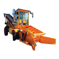
Pointers
Figure 4-3. Moldboard Pointers
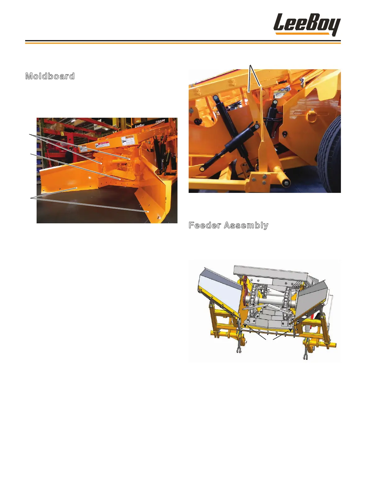
Feeder Assembly
Adjust the feeder assembly to a height of approximately
two inches off the transition plate using the following
procedure (Figure 4-4):
2”
Figure 4-4. Feeder Assembly Height
1. Lift front of feeder using a lifting hoist.
2. Loosen jam nuts on both sides of the feeder
assembly support rods. (Figure 4-4)
NOTE: Ensure cam rollers are not touching while
making this adjustment.
MACHINE ADJUSTMENTS
Moldboard
It is important to set-up the moldboard before operating
the loader. Check the adjustments daily to ensure there
is no interference between the moldboard and the
feeder chain assembly. (Figure 4-2)
1
2
3
Figure 4-2. Moldboard and Feeder Chain Assembly
1 - Feeder Chains
2 - Feeder Plate
3 - Cutting Edges
You will need to adjust both the feeder assembly and the
cam roller assembly to set up the moldboard properly.
To prepare machine for these adjustments:
1. Park machine on a at surface.
2. Raise the rear of the main conveyor into the work
position using the main conveyor lift switch on the
operating control console. (Page 3-3)
3. Insert safety pins to desired operating height.
(Page 4-4)
4. Using the conveyor and moldboard lift control levers
(Page 3-4), lower the cutting edges so that all ve
cutting edges are at on the ground. (Figure 4-2)
5. Align the the moldboard pointers. (Figure 4-3)
Operation
3000C Force Feed Loader4-6