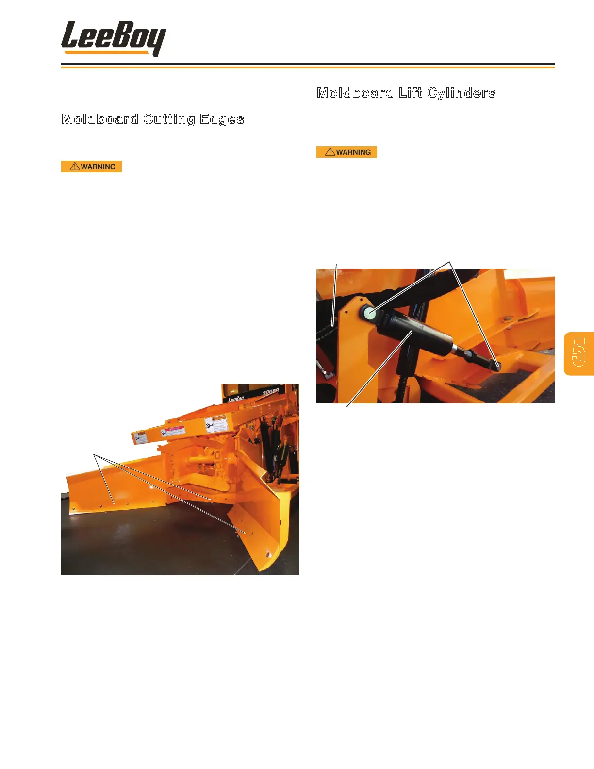
Moldboard Lift Cylinders
The moldboard cylinders are located on both sides of
the machine behind the moldboard. These cylinders
should be replaced if damaged or inoperable.
Before breaking circuit connections,
ensure power is off and system pressure has been
released. Lower all vertical cylinders, discharge any
accumulators, and block any load that could move
and generate pressure.
NOTE: Plug and cap all lines and ports when
disconnected to prevent entry of dirt into
the system.
Hoses
Cylinder
Pins
Figure 4-22. Moldboard Lift Cylinders
1. Place a container under the cylinder to catch any
hydraulic oil when the lines are disconnected.
2. Disconnect and label the two hoses connected to
cylinder ttings. (Figure 5-22)
3. Remove the two clevis pins and cotter pins,
securing cylinder.
4. Remove cylinder from machine.
5. Install new cylinder.
6. Reinstall the two clevis pins and cotter pins.
7. Reconnect the two hydraulic hoses.
8. Add hydraulic oil, if needed.
9. Start the engine and operate the cylinder to check
for any leaks and proper operation.
REPLACING COMPONENTS
Moldboard Cutting Edges
The moldboard cutting edge needs to be replaced if
worn. (Figure 5-21)
Engine must be turned off and the
wheels blocked to prevent motion when servicing the
machine. Also block moldboard to prevent injury.
Replace the cutting edge as follows:
1. Raise the moldboards off the ground.
2. Turn off engine and block the wheels to prevent
movement. Block moldboard off the ground as high
as possible.
3. Clean the area around the cutting edge.
4. Remove the four plow bolts, washers and nuts
securing the cutting edge. Remove cutting edge.
5. Attach a new cutting edge with the plow bolts,
washers and nuts .
6. Torque nuts to 105 ft-lb (145 N.m).
7. Lower moldboard, ensuring it is at on the surface.
Moldboard Cutting Edges
Figure 4-21. Moldboard Cutting Edges
5
Maintenance
3000C Force Feed Loader 5-19