5-28 LeeBoy 8520C Conveyor Paver
Maintenance
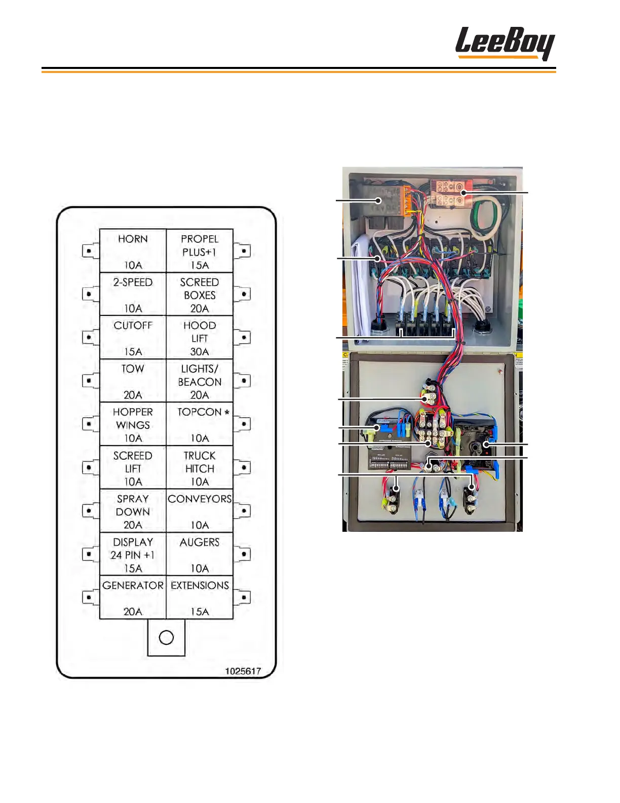
Fuse PanelFuse Panel
The electrical system is protected from overload
damage by fuses. If an electrical component fails to
operate, check the fuse box panel rst to ensure that
a fuse has not “blown.” A blown fuse is an indication
that there is an overload that needs to be corrected.
The fuse panel is located inside the main control box.
(Figure 5-31)
Figure 5-31. Fuse Panel
* TopCon controller system if equipped with this
option.
Electric Heat Control BoxElectric Heat Control Box
The electric heat control box contains the element
breakers and main outputs for the screed heating
system. Powered at 240 VAC, each element has two
circuit breakers. (Figure 5-32)
1
2
3
4
5
9
6
7
8
10
Figure 5-32. Electric Heat Elements
1 - Power Control Relays
2 - Heating Element Relays
3 - Element Circuit Breakers
4 - Power Crown Switch
5 - Cycling Timer
6 - Automatic/Manual Power Toggle Button
7 - Toggle for Left/Right Endgates
8 - Wire Junction Block
9 - Manual Mode Timer
10 - Heat ON Button