5555
LeeBoy 8520C Conveyor Paver 5-29
Maintenance
ALWAYS be careful when working with
electrical components to avoid electrical shock. The
heat box is high voltage (220V), therefore, take extra
precautions to avoid electrical shock that could
cause serious injury or even death.
NOTE: Control boxes are manufactured to t all
screed and paver combinations. If not all
plugs are connected to wires, it may be
normal. Be sure to keep unused plugs
covered with mating protective caps.
• Each element output consists of two wires--one
connects to the L-1 circuit and the other to the L-2
circuit. (Figure 5-32)
• Each breaker has two terminals--one is connected
to the main input and the other terminal to an element
output wire.
• The L-1 circuit is the left bank of element breakers.
• The L-2 circuit is the right bank of element breakers.
Heating element relays “make” or “break” the circuit to
each element to start or stop the heating cycles. When
the HEAT ON button is depressed, 12VDC is momen-
tarily applied to the main timer relay to start the timing
cycle.
Element Resistance TestingElement Resistance Testing
The breakers are wired into each leg of each element. If
an element has a fault, either in the wiring, or in the ele-
ment itself, the breaker will trip and power will no longer
be applied to that leg of the element.
When a breaker in the control box has “tripped,” there
may be a problem in the wiring or an element in the
circuit.
The breakers can be manually reset by depressing the
trip button back into place when they are extended. If
the breaker still does not reset, you need to test or pos-
sibly replace an element.
If the element is functioning correctly, you should read a
resistance between the connector pins when testing. A
faulty element will show high resistance, indicating a bad
element.
To test the element:
1. Disconnect elements one at a time from the
connection point on the lower side of the control
box, keeping track of connector placement.
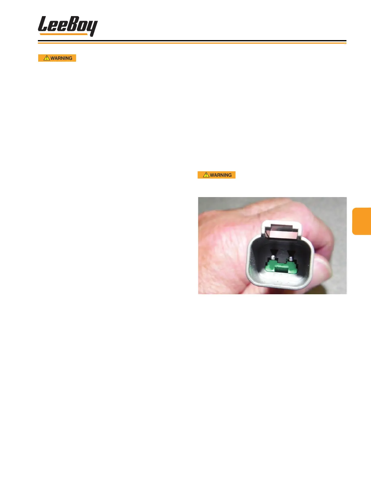
2. Using an ohm meter, test the resistance through the
element between the two pins in the plug. (Figure
5-33)
NOTE: You do not have to test the plug attached to
the lower side of the control box.
3. Before replugging the element, check each wire
pin with an ohm meter test lead, placing the lead
on a steel section of the screed frame. If there is
any continuity through the element to the frame, the
element must be replaced.
DO NOT operate an element with a
known electrical shortage. Replace faulty elements
and wiring immediately.
Figure 5-33. Plug